Section IV
Model 333AI334,
linear. The input impedance
is
kept linear
by
use of
local positive feedback from the source of A2Ql to
the gate of A2Ql and to the protective diodes A2CR2
and A2CR3. Thus signals with
a
large source imped-
ance can
be
measured accurately. Overall induced
distortion
is
further minimized
by
a high open loop
gain and 100% negative feedback. The high open loop
gain
is
achieved
by
local
positive feedback from the
emitter
of
A2Q3 to the collector
of
A2Q2. Overall
negative feedback from the emitter circuit
of
A2Q4
to the source of A2Ql results in unity gain from the
impedance converter.
4-16. The bias
points
of the transistors
in
the imped-
ance converter
are
selected to minimize instrument
induced distortion. A2Q1, an extremely low noise,
high impedance field
effect
transistor,
is
the major
component that makes linearity of the impedance con-
verter independent
of
the
signal
source impedance.
4-17. REJECTION AMPLIFIER CIRCUIT.
(Refer to
Figures
7-3
and
7-5)
4-18. The rejection amplifier circuit consists of the
preamplifier (A3Q1
thru
A3Q3), the Wien bridge
resistive leg and auto control loop (A5Q1 thru A5Q9
with associated lamp and photocell), the reactive leg
and auto control loop (A5Q10 thru A5Q18 with associ-
ated lamp and photocell), and the bridge amplifier
(A3Q4 thru A3Q6).
4-19. PREAMPLIFIER CIRCUIT.
4-20. The signal from the impedance converter
is
applied to the preamplifier, which
is
used during SET
LEVEL
and DISTORTION measuring operations.
Negative feedback from the junction of A3R10 and
A3Rll
is
applied to the junction of A3R2 and A3C2 to
establish the operating point for A3Q1. Negative
feedback from
the emitter
of
A3Q3
is
applied to the
emitter
d
A3Q1 to stabilize the preamplifier. The
preamplifier, like the impedance converter,
is
designed for high open loop
gain
and low closed loop
gain
to minimize
instrument
induced distortion.
4-21. WIEN BRIDGE CIRCUIT.
4-22. In
the distortion measuring operationthe Wien
bridge
circuit
is
used as
a
rejection
filter
for the
fundamental frequency of the input
signal.
With the
FUNCTION selector, S1, inthe DISTORTION position,
the Wien brldqe
is
connected
as
an
interstage coupling
network between
the preamplifier circuit and the
bridge amplifier circuit. The bridge
is
tuned to the
fundamental frequency
of
the input signal by setting
the FREQUENCY RANGE selector,
S4,
for the appli-
cable frequency
range,
andtuning the capacitors C4A
through C4D. The bridge circuit
is
balanced by ad-
justing
the
COARSE balance control, R4, andthe FINE
balance control, R5.
In
the AUTOMATIC MODE fine
tuning and balancing
are
accomplished
by
photoelectric
cells which
are
in the resistive and reactive legs of
the Wien bridge. The error signals for driving the
photocells
are
derived by detecting the bridge output
using the input signal
as
a
reference,
4-23. When the Wien bridge
is
not tuned exactly to
the frequency to be nulled, aportion of the fundamental
4
-2
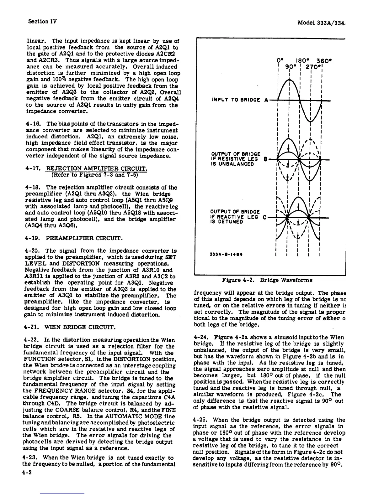
INPUT TO BRIDGE
OUTPUT OF BRIDGE
IF RESISTIVE LEG
IS
UNBALANCED
OUTPUT
OF
BRIDGE
IF
REACTIVE LEG
IS DETUNEO
Figure
4-2. Bridge Waveforms
frequency will appear
at
the bridge output. The phase
of this
signal
depends
on
which leg
of
the bridge
is
nc
tuned,
or
on the relative errors in tuning
if
neither
if
set
correctly.
The magnitude of the signal
is
propor
tional to the magnitude of the tuning error
of
either
0.
both legs of the bridge.
4-24.
Figure
4-2a shows
a
sinusoidinputtothe Wien
bridge.
If
the resistive leg of the bridge
is
slightly
unbalanced, the output of the bridge
is
very small,
but has the waveform shown
in
Figure 4-2b and
is
in
phase with the input.
As
the resistive leg
is
tuned,
the signal approaches zero amplitude at null and then
becomes larger, but 180° out of phase, if the
null
position
is
passed.
When the resistive leg
is
correctly
tuned and the reactive leg
is
tuned through null,
a
similar waveform
is
produced, Figure 4-2c. The
only difference
is
that the reactive signal
is
90°
out
of phase with the resistive
signal.
4-25. When
the
bridge output
is
detected using the
input signal
as
the
reference, the error
signals
in
phase
or
1800 out of phase with the reference develop
a voltage that is used to vary the resistance
in
the
resistive leg
of
the bridge, to tune it to the correct
null position. Signals of the form in Figure 4-2c do not
develop any voltage,
as
the resistive detector is in-
sensitive to inputs differingfrom the reference by
90°.