Model 333A/334A Section
V
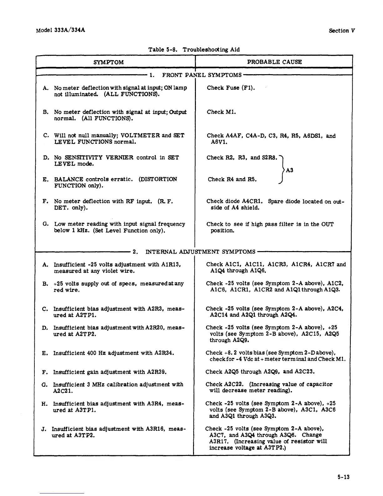
Table 5-8. Troubleshooting Aid
SYMPTOM
I
PROBABLE CAUSE
1.
FRONT
PA
A.
B.
C.
D.
E.
F.
G.
No
meter deflection with signal
at
input;
ON
lamp
not illuminated. (ALL FUNCTIONS).
No
meter deflection with
signal
at
input;
Output
normal. (All FUNCTIONS).
Will nat null manually; VOLTMETER and SET
LEVEL FUNCTIONS normal.
No
SENSITIVITY
VERNIER
control in SET
LEVEL mode.
BALANCE controls erratic. (DISTORTION
FUNCTION only).
No
meter deflection with RF input.
(R.
F.
DET. only).
Low meter
reading
with input
signal
frequency
below
1
kHz.
(Set Level Function only).
2. MTERNALAATl
A.
B.
C.
D.
E.
F.
G.
H.
J.
Insufficient -25 volts adjustment with AlR13,
measured
at
any violet wire.
+25 volts supply
out
of specs, measuredatany
red wire.
Insufficient bias adjustment with A2R3, meas-
ured
at
A2TP1.
Insufficient bias adjustment with A2R20, meas-
ured
at
A2TP2.
Insufficient 400
Hz adjustment with A2R34.
Insufficient gain adjustment with A2R39.
Insufficient 3
MHz
calibration adjustment with
A2c21.
Insufficient bias adjustment with A3R4, meas-
ured
at
A3TP1.
Insufficient bias adjustment with A3R16, meas-
ured
at
A3TP2.
EL
SYMPTOMS
Check Fuse (Fl).
Check
M1.
Check AIAF, CIA-D, C3, R4,
R5,
A6DS1, and
A6V1.
CheckR2, R3, andS2R8.
Check R4 and
R5.
1a3
Check diode A4CR1. Spare diode located
on
out-
side of A4 shield.
Check to see
if
high pass filter
is
in the
OUT
position.
TMENT
SYMPTOMS
Check AlC1, AlC11, AlCR3, AlCR4, AlCR? and
A1Q4 through AlQ6.
Check -25 volts
(see
Symptom 2-A above), AlC2,
AlC6, AlCR1, AlCR2 and AlQlthroughAlQ3.
Check -25 volts (see Symptom 2-A above), A2C4,
A2C14 and A2Ql through A2Q4.
Check -25 volts (see Symptom 2-A above), +25
volts
(see
Symptom 2-B above), A2C15, A2Q5
through A2Q9.
check for -4 Vdc
at
+
meter terminal and Check
M1.
Check +8.2 volts bias (see Symptom 2-Dabove),
Check A2Q5 through A2Q9, and A2C23.
Check A2C22. (Increasing value
of
capacitor
will decrease meter reading).
Check -25 volts
(see
Symptom 2-A above), +25
volts (see Symptom 2-B above), A3C1, A3C6
and A3Q1 through A3Q3.
Check -25 volts
(see
Symptom 2-A above),
A3C7, and A3Q4 through A3Q6. Change
A3R17. (Increasing value
of
resistor
wilI
increase voltage
at
A3TP2.)
5-13