Section
V
Model 333A/334A
C.
d.
e.
f.
e.
h.
Set test oscillator frequency
to
500
Hz,
and
adjust amplitude
for
indication
of
+2
d~
on
333A/334A meter.
Set 333A/334A FUNCTION switch to DIS-
TORTION.
Adjust 333A/334A frequency
dial
vernier and
BALANCE
controls for minimum meter in-
dication. When
meter
indication
is
lessthan
10%
of
SET
LEVEL
indication,
set
MODE
switch to AUTOMATIC.
Reduce 333A/334A METER RANGE setting
as
necessary
to
maintain on-scale meter
indication.
333A/334A meter indication should
be
at
least
70
dB
below
+2
dB
reference.
Repeat steps b
through
g
with 333A/334A
and
test
equipment frequencies
set
to
250
kHz
and
600
IrHz.
333A/334A meter indi-
cation should
be
at
least
64
dB
below
+2
dB
reference.
5-13. FREQUENCY CALIBRATION ACCURACY
CHECK.
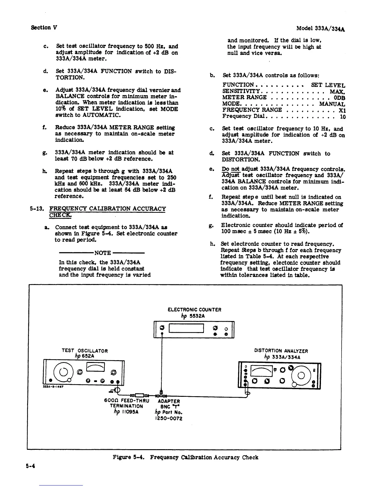
a.
Connect
test
equipment to 333A/334A
as
shown in
Figure
54.
Set electronic counter
to read period.
b.
C.
6
e.
f.
g*
h.
NOTE
In
this check, the 333A/334A
frequency
dial
is
held constant
and monitored.
If
the dial
is
low,
the input frequency
will
be
high
at
null and vice versa.
Set 333A/334A controls
as
follows:
FUNCTION
-
SET
LEVEL
SENSITIVITY..
...........
MAX.
METERRANGE
............
ODB
MODE..
.............
M.ANUAL
FREQUENCYRANGE
..........
Xl
Frequency
Dial.
.............
10
Set test oscillator frequency to
10
Hz,
and
adjust amplitude
for
indication of
+2
dB
on
333A/334A meter.
Set 333A/334A FUNCTION switch to
DISTORTION.
Do
not adjust 333A/334A frequency controls.
mjx
test
oscillator frequency and 333A/
334A
BALANCE
controls for
minimum
indi-
cation on 333A/334A meter.
Repeat stepe until
best
null
is
indicated on
333A/334A. Reduce METER RANGE
setting
as
necessary to maintainon-scale meter
indication.
Electronic counter should indicate period
of
100 meec
f
5
m8ec
(10
Hz
f
5%).
Set
electronic counter
to
read frequency.
Repeat Steps
b
through
f
for
each frequency
listed
in
Table
5-4.
At each respective
frequency
setting,
electonic counter should
indicate
that
test
oscillator
frequency
ie
and the
input
frequency
is
varied within tolerances listed
in
table.
ELECTRONIC COUNTER
hp
5532A
TEST OSCILLATOR DISTORTION ANALYZER
hp
652A
hp
333A/334A
d
0-0
09
clu
0
0
U14-I-14S7
6oon
FEED-THRU
ADAPTER
hp
11095~
hp
Port
NO.
TERMINATION BNC
"Tu
1250-0072
Figure
5-4.
Frequency
Calibration
Accuracy Check
5
-4