Model 333A/334A
SENSITIVITY
Switch
Position
4
Position
3
Position
2
Position
1
C.
d.
e.
f.
g*
h.
TEST OSCILLATOR
ADJUST
OUTPUT (Increase) FOR
9
mV
+lo
dB
ac4
+20
dB
s2c3
+30
dB
s2c2
+40 dB
ac1
SENSITIVITYVERNlER..
.....
MIN.
SENSITIVITY.
..
.1
step counterclochise
METER RANGE
.
,
.
.
,
. .
SET LEVEL
MODE..
.............
MANUAL
FREQUENCY RANGE
........
X1K
Frequency
Dial.
............
60
Turn slot
on
trimmer capacitor C3 parallel
with side casting of instrument.
Set test oscillator frequency to
60
kHz,
and
adjust amplitude for indication
of
+2
dB
on
333A/334A meter.
Set 333A/334A COARSE and
FINE
BALANCE
controls to center of range.
Set 333A/334A FUNCTION switch to
DIS-
TORTION.
Adjust
test
oscillator frequency vernier con-
trol and C3 for definite null indication on
meter of 333A/334A. Reduce METER
RANGE setting
as
necessary to maintain
on-scale reading.
Observe electronic counter indication.
If
test
oscillator frequency
is
not between
57
kHz
and
63
kHz,
333A/334A frequency
dial
is
out
of
tolerance. Follow steps
be-
low to bring frequency
dial
within tolerance:
Set 333A/334A controls
as
in
step b.
Set test oscillator frequency for elec-
tronic counter indication
of
60.00
HI,
and adjust amplitude for indication of
+2
dB
on meter
of
333A/334A.
Set 333A/334A COARSE and
FINE
BAL-
ANCE controls to center of range.
Adjust 333A/334A frequency
dial
vernier
control for
definite
null.
Remove knob from frequency
dial.
Do
not change tuning capacitor,
C4,
setting
Loosen retaining screws in frequency
dial
plate, and slip
dial
until 60
is
dir-
ectly under
mark
on indicator.
Be
careful not to change
C4
setting.
Tighten retaining screws and replace
knob.
5-30. SENSITIVITY SWITCH CALIBRATION.
a.
Connect test oscillator to 333A/334A
ae
shown
in
Figure 5-1.
NOTE
Selector positions for the SENSI-
TMTY selector
will
be
referred to
as
follows:
MIN
=
Position
1,
next
step
=
Position
2,
etc., to MAX
=
Position
6.
b.
C.
d.
e.
f.
8.
Section
V
Set
Distortion Analyzer controls
as
follows:
FUNCTION..
........
SETLEVEL
METER RANGE
.......
0.01
VOLTS
SENSITIVITY
..........
Position 5
SENSITIVITY VERNIER
.......
MAX.
Set test oscillator frequency
to
400
Hz,
ad-
just amplitude
for
indication of
9
mV on
333A/334A
meter.
Set
a
reference on meter
of
test oscillator
and
use
amplitude control to maintain
set
reference whenever frequency of oscillator
is
varied.
Set test oscillator frequency to 100
kHz.
Adjust S2C5 for 333A/334A meter indication
of
9
mV.
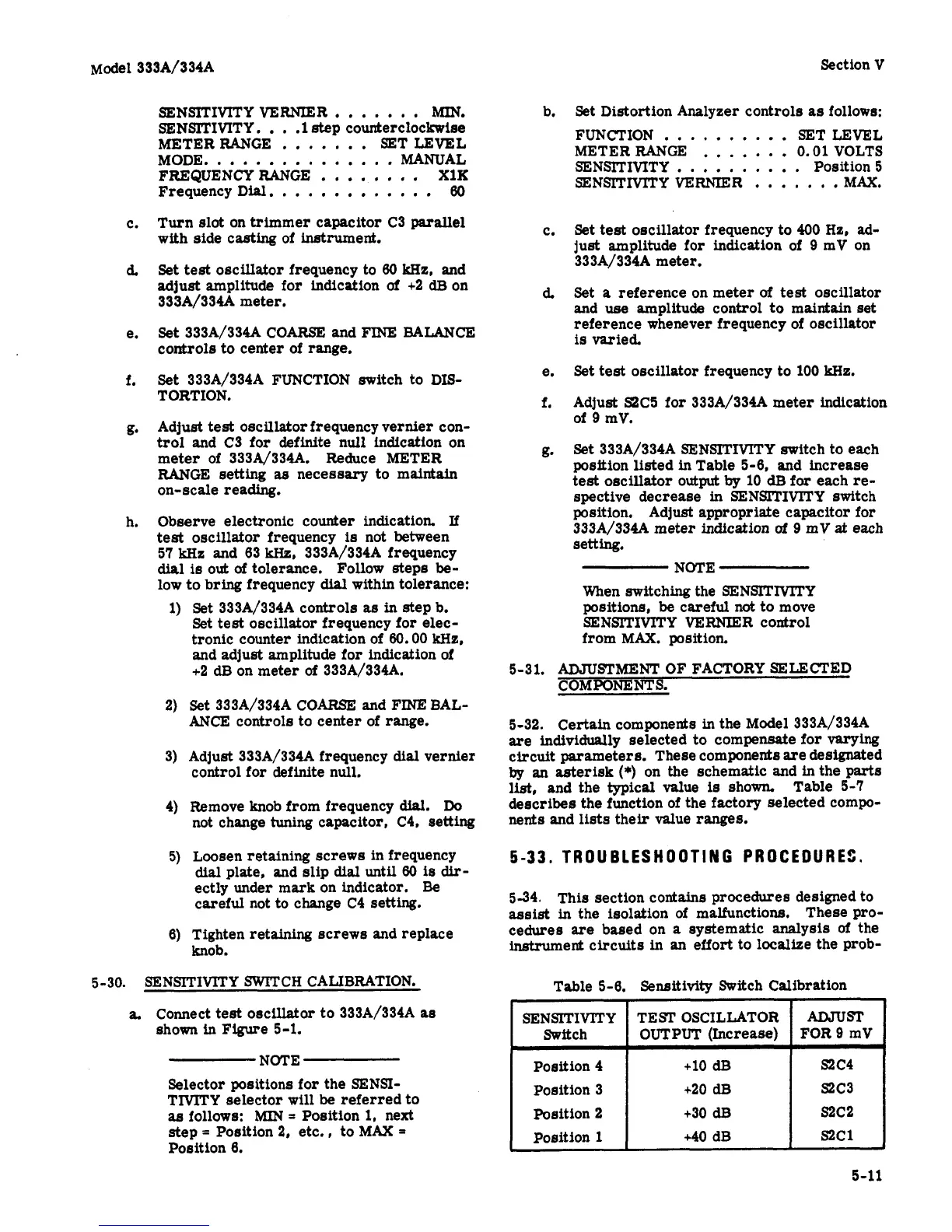
Set 333A/334A SENSITIVITY switch to each
position listed in Table 5-6, and increase
test oscillator
output
by
10
dB
for
each re-
spective decrease
in
SENSITIVlTY switch
position. Adjust appropriate capacitor for
333A/334A
meter indication
of
9
mV
at
each
setting.
NOTE
When switching the SENSITMTY
positions,
be
careful not to move
SENSITIVITY VERNIER control
from
MAX.
position.
5-31. ADJUSTMENT
OF
FACTORY SELECTED
COMPONENTS.
5-32. Certain components in the
Model
333A/334A
are
individually selected to compensate for
va.rying
circuit parameters. These components are designated
lqr
an
asterisk
(*)
on the schematic and in the
parts
list,
and the typical
value
is
shown
describes the function of the factory selected compo-
nents
and lists their value
ranges.
Table
5-7
5-33,
TRO
U
BLES
H
0
OTI
N
G
PR
0
CEDU
R
Et.
5-34. This section contains procedures designed to
assist
in the isolation of malfunctions, These
pro-
cedures
are
based on
a
systematic
analysis
of
the
instrument circuits in
an
effort to localize the prob-
Table
5-6.
Sensitivity Switch Calibration
5-11