Section
III
3-23. METER INDICATION.
3-24. The 333A/334A meter
is
calibrated to indicate
in
both dB and volts.
It
is
interesting to notethat the
METER RANGE markings differ from most ac volt-
meter range markings.
On
most
ac
voltmeters
(600
ohms)
0
dB
corresponds
to
the
1
volt
range.
This
is
not
true
in the case
of
the 333A/334A. Since the
instru-
ment
is
primarily
a
distortion analyzer, measurements
are
in
dB (relative measurement) rather than
in
dBm
(absolute measurement).
Zero dB on the 333A/334A
corresponds to 0.3 volt range rather than
the
1
volt
range. This allows a10
dB
greater
dynamic
range
of
distortion measurements.
Model 333AI334A
3-30. 333A/334A
WT”H
OPTION 01.
3-25.
E
measurements
are
to
be
made in dBm, 10
dB
must
be
subtracted from the METER RANGE
setting.
Thus
0
dB
becomes the -10 dBm
range
for absolute
power measurements.
Zero dBm
is
equal
to
1
milli-
watt dissipatedby any impedance andinthis particular
case
is
800
ohms.
The +10 DECIBELS marking on the
meter
face
indicates
that when voltmeter measurements
are
being made, the indication (METER RANGE plus
meter indication)
is
10
dB
greater
than when power
(dBm) measurements
are
being made.
3-26.
In
short, when distortion and voltage measure-
ments
are
being made, utilize the instrument METER
RANGE and meter scale
as
they
exist.
For absolute
power measurements in dBm, simply subtract 10
dB
from the METER RANGE
setting.
3-27. USE OF OUTPUT TERMINALS.
3-28.
InVOLTMETERand SET LEVEL functions, the
333A/334A can
be
used
as
a
low distortion, wide-band
amplifier. A portion of the meter
input
(0.1
V
rms
open
circuit for
full
scale meter deflection
is
provided
at
the
OUTPUT terminals.
3-29.
In
DISTORTION function, the distortion (0.1
V
rms open circuit forfull
scale
deflection)
is
provided
at
the OUTPUT terminals for monitoring purposes.
NOTE
The INPUT terminal and the
OUTPUT terminal should not be
connected directly together when
making low level measurements.
These terminals
are
isolated from
each other
by
1
ohm which reduces
the
effects
of
common mode voltages.
3-31. Operating procedures for the 333A/334A with
Option01
are
the same as for the standard instrument.
The onlydifference between the standard and optional
instrument
is
that the Option 01 has
a
special
meter
and meter amplifier which
is
compensated to respond
to
W
(volume
unit)
characteristics.
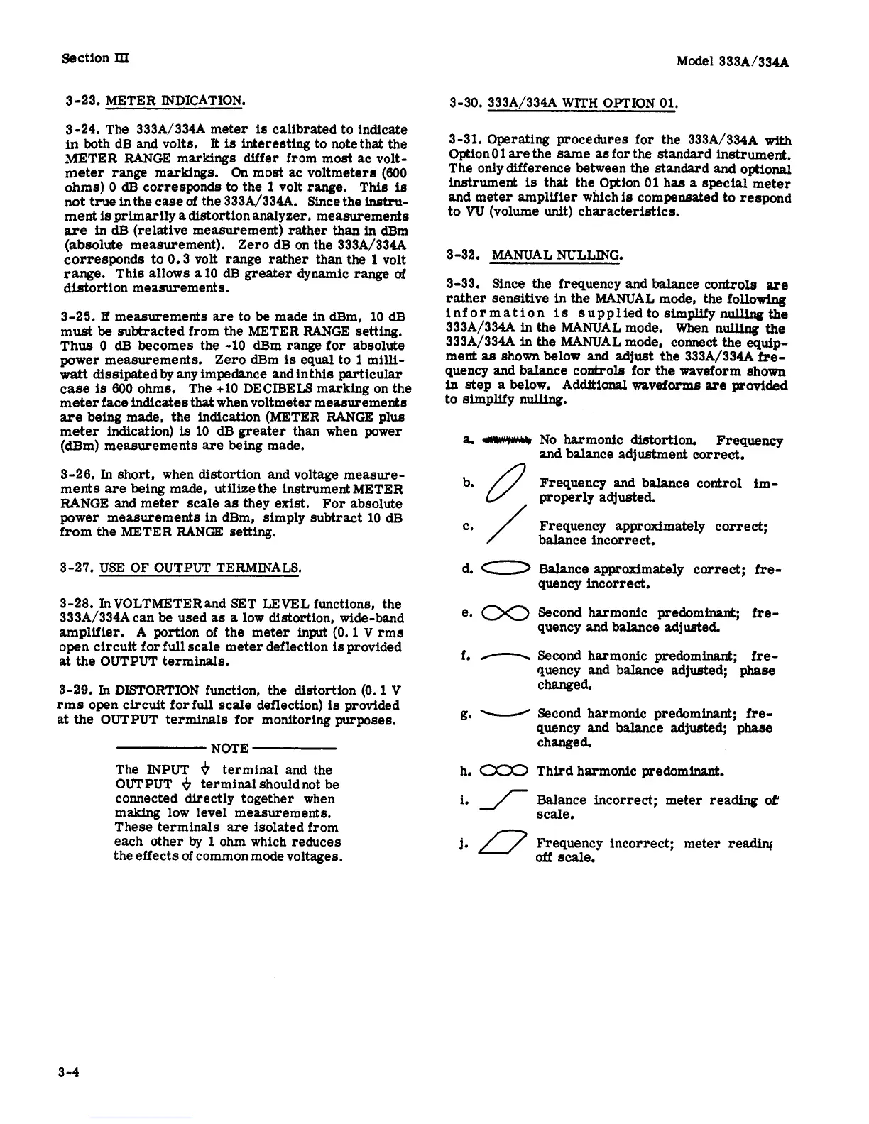
3-32. MANUAL NULLING.
3-33. Since the frequency and balance controls
are
rather
sensitive in
the
MANUAL mode,
the
following
information
is
supplied to
simplify
nulling the
333A/334A
in
the MANUAL mode. When nulling
the
333A/334A
in
the MANUAL mode, connect
the
equip-
ment
as
shown
below
and
adjust
the
333A/334A
fre-
quency
and
balance controls for the waveform shown
in
step
a
below. Additional waveforms
are
provided
to simplify nulling.
No harmonic
dietortion.
Frequency
and
balance adjustment correct.
Frequency and balance control
im-
properly adjusted.
Frequency approximately
correct;
balance
incorrect.
Balance
approximately correct;
fre-
quency incorrect.
Second harmonic predominant;
fre-
quency and balance adjusted.
Second harmonic predominant;
fre-
quency and balance
adjusted;
phase
changed.
Second harmonic predominant;
fre-
quency and balance
adjusted;
phase
changed.
Third harmonic predominant.
Balance incorrect; meter reading
&
scale.
Frequency incorrect; meter
readin(
off
scale.
3 -4