Section
V
Model
333A/334A
TO
GROUND
(f)
TERMINAL
(ON
REAR
PANEL
OFTHE
hp
204C)
L
WER
SUPPLY
ps:
p
6515A
1
'I
DIGITAL MULTIMETER
hp
3465~
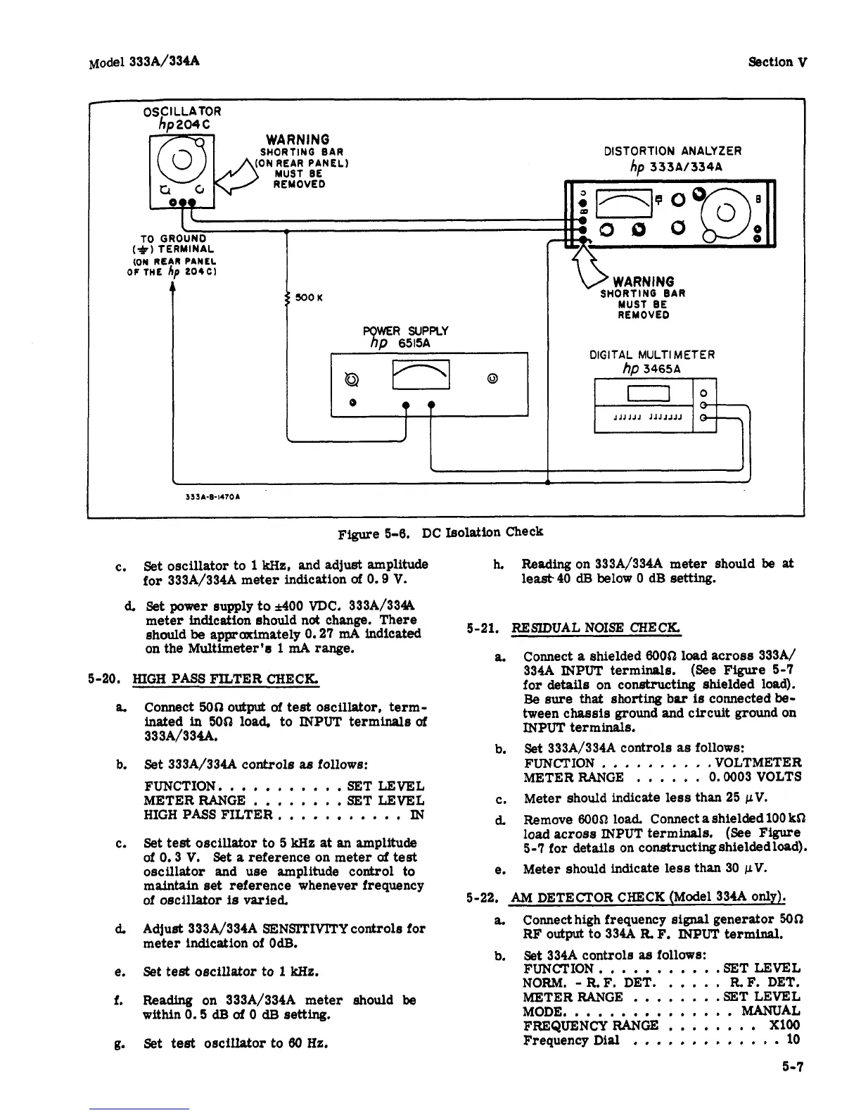
Ffgure
5-6.
DC
Isolation Check
c.
Set oscillator to
1
kHz,
and adjust amplitude
for
333A/334A
meter indication
of
0.9
V.
d.
Set
power
supply
to
A00
VDC.
333A/3344
meter indication should
not
change. There
should
be
approximately
0.27
mA
indicated
on the Multimeter's
1
mA range.
5-20.
HIGH
PASS FILTER CHECK.
am
b.
C.
d.
e.
f.
g*
Connect
500
output
of
test
oscillator, term-
inated
in
500
load,
to
INPUT terminals
of
333A/334A.
Set
333A/334A
controls as
follows:
FUNCTION.
.
. .
.
.
.
.
. . .
SET LEVEL
METERRANGE
.
. . .
.
.
. .
SET LEVEL
HIGH
PASS FILTER.
,
.
.
.
.
.
.
. .
.
IN
Set test oscillator to
5
We
at
an
amplitude
of
0.3
V.
Set
a
reference on meter
of
test
oscillator and use amplitude control to
maintain set reference whenever frequency
of
oscillator
is
varied.
Adjust
333A/334A
SENSTMTY
controls for
meter indication of
OdB.
Set test oscillator to
1
We.
Reading
on
333A/334A
meter
should
be
within
0.5
dB
of
0
dEJ
setting.
Set
test
oscillator
to
60
Hz.
h.
Reading on
333A/334A
meter should
be
at
least40
dB
below
0
dB setting.
5-21.
RESIDUAL
NOISE
CHECK.
a.
Connect
a
shielded
60051
load across
333A/
334A
INPUT terminals. (See
Figure
5-7
for
details
on constructing shielded load).
Be
sure that
shorting
bar
is
connected
be-
tween chassis ground and circuit ground on
INPUT
terminals.
Set
333A/334A
controls
as
follows:
FUNCTION
,
.
.
,
. . .
.
,
. VOLTMETER
METER RANGE
.
.
.
,
.
.
0.0003
VOLTS
Meter
should indicate less than
25
pV.
Remove
60052
load. Connect
a
shielded 100
k52
load across INPUT terminals.
(See
Figure
5-7
for details
on
constructingshieldedload).
Meter should indicate
less
than
30
pV.
b.
c.
d.
e.
5-22.
AM
DETECTOR CHECK (Model
334A
OnlJr).
a.
b.
Connect high frequency
signal
generator
5052
RF
output
to
334A
R.
F.
INPUT
terminal.
Set
33449
controls
as
follows:
FUNCTION.
. . . .
.
. .
.
.
.SET LEVEL
NORM.
-
R.F.
DET.
. .
,
.
.
R
F.
DET.
METER RANGE
.
.
.
.
.
.
.
.SET LEVEL
MODE,.
. .
,
.
.
.
.
, ,
.
,
. .
MANUAL
FREQUENCYRANGE
,
.
.
,
.
,
.
.
XlOO
Frequency Dial . . .
,
,
.
.
.
. .
.
,
.
10
5-7