TRO
U
BLESH
0
OTlN
G
INFORM AT10
N
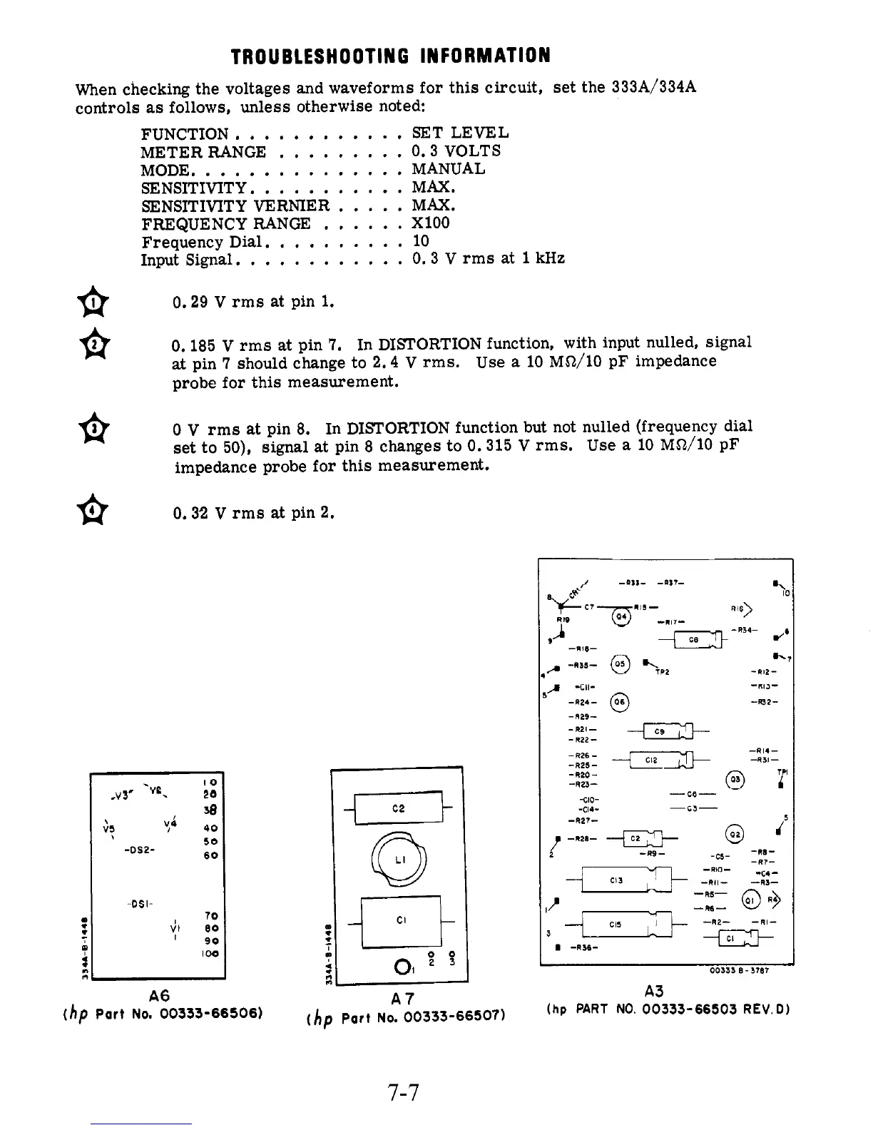
When checking the voltages and waveforms for this circuit, set the 333A/334A
controls
as
follows, unless otherwise noted:
FUNCTION.
...........
SET LEVEL
METER RANGE
.........
0.3 VOLTS
MODE,
..............
MANUAL
SENSITIVITY
...........
MAX.
FREQUENCYRANGE
......
XlOO
Frequency Dial.
.........
10
Input Signal.
...........
0.3 V rms
at
1
kHz
SENSITIVITY VERNIER.
....
MAX.
0.29
V
rms at pin
1.
fi
0.
185
V
rms
at
pin
7.
In DISTORTION function, with input nulled, signal
at
pin
7
should change to 2.4
V
rms. Use
a
10 MS2/10 pF impedance
probe for this measurement.
fi
0
V
rms
at
pin
8.
In DISTORTION function but not nulled (frequency dial
set to 50), signal
at
pin
8
changes to 0.315 V rms. Use
a
10
MS2/10
pF
impedance probe for this measurement.
0.32
V
rms
at
pin
2.
IO
.v3'
-ye.
ee
Yi
40
38
50
60
-CIS.?-
-DSI
(1
n
n
A6
3
-cII-
-"lJ-
-R24-
@
-m2-
-829-
-R2l-
-n22-
-RI4-
CIZ
J
+31-
-R26-
-R25-
-R20-
-823-
00333
B
-
3707
A3
(hp
PART
NO.
00333-66503
REV.D)