0
R
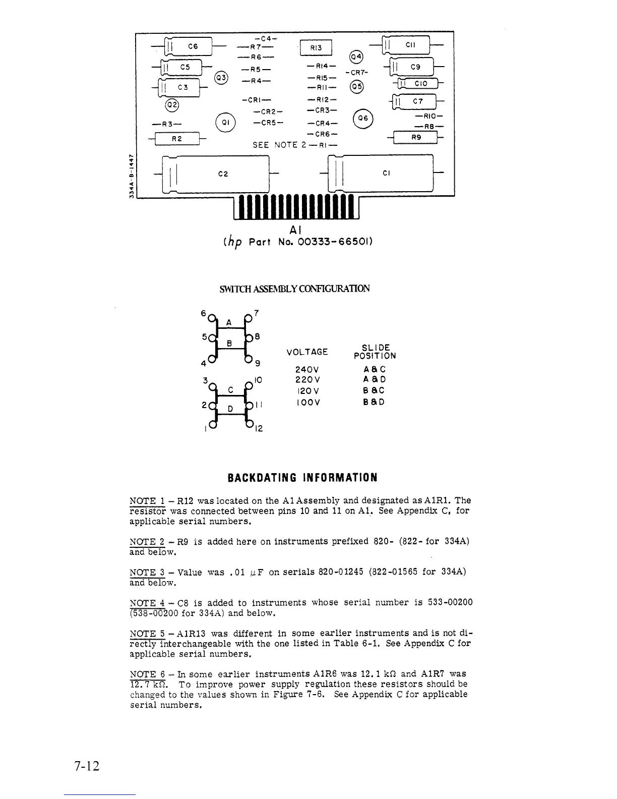
SWITCH
ASSEhIBLY
CONFIGUILL\TION
-c4-
*Fk
-R7-
-R6-
+Tk
-R5-
+y'@
-R4-
-RII-
@
-Rl4-
-Rl5-
-CR7-
fpz-)-
-CRI- -Rl2-
-@TI-
sek3-
-RIO-
-RE-
-CR4-
-CR2-
-CR5-
-
CR6
-
SEE
NOTE
2-Rl-
-cR3-
c3
@
-R3-
c3
!{-7--l
g7-1
2
3]-$
I
12
V
0
LT
AG
E
240V
220
v
120
v
I
oov
SLIDE
POSITION
ABC
ABD
B8D
B
ac
BACK
OAT
IN
G
IN
F
0
R
M
AT1
0
N
NOTE
1
-
R12 was located
on
the A1 Assembly and designated
as
A1R1. The
resistor
was
connected between pins
10
and
11
on Al. See Appendjx C, for
applicable serial numbers.
NOTE
2
-
R9
is
added here on instruments prefixed 820- (822- for 334A)
and be low.
NOTE
3
-
Value was
.01
pF
on
serials
820-01245 (822-01565 for 334A)
and below.
NOTE
4
-
C8
is
added to instruments whose serial number
is
533-00200
(538-00200
for 334A) and below.
NOTE
5
-
A1R13 was different in some earlier instruments and
is
not di-
rectly interchangeable with the one listed in Table
6-1.
See Appendix C for
applicable serial numbers.
NOTE
6
-
In
some earlier instruments
A1R6
was 12.1 kS1 and A1R7 was
12.7
kS2.
To improve power supply regulation these resistors should be
changed
to
the values
shown
in Figure
7-6.
See Appendix
C
for applicable
serial numbers.
7-12