Appendix C
Model 333A/334A
CHANGE
61
CHANGE
#2
Manual
Backdating
Changes
Model
333A/334A Page 2
Add
AlC8,
0150-0085
C:
fxd cer 0.0022 pF 500 vdcw.
Change A2R51
to
0683-7535
R
kd comp 75
kn
1/4
W
*5%.
Change value
of
A2Ft51 to 75
kh
Add Capacitor, AlC8, 0.0022 pF, between
cathode
of
AlCEM
and
base
of
AlQ5.
Change A2C12
to
0150-0084
C:
fxd cer 0.1 pF
40%
-20%
50
vdcw.
Change A2Rl6
and
A2R28 to 0683-1005 R: fxd comp 10
ohms
*5%
1/4
W.
Table 6-1:
Figure 7-4:
Figure 7-6:
Table 6-1:
change
A2C2O
to
0180-1735
C:
hrd 0.47
pF
*lo%
35
Vdcw.
NOTE
1
Exclrrding:
822-0178?, -01791, -01792, -01794, 41796, -01799
tb~
-01802,
-01806
thru
-01808,
-01811, -01813, -01817, -01823, -01824, -01825, -01827, -01829, -01830, -01832,
-01834, -01835, -01837, -01839, -01842, -01844, -01845, -01848, -01851, -01852,
-01853, -01855, -01858, -01861, and -01863.
NUTE
2 Excluding:
910-01493, -01494, -01495, -01497, -01500,
-01501,
-01503, -01504, -01507, -01508,
-01509, -01510, 41512, -01514, -01515, -01516, -01518, -01520, -01521,
and
-01524.
CHANGE
63
CHANGE #4
CHANGE
65
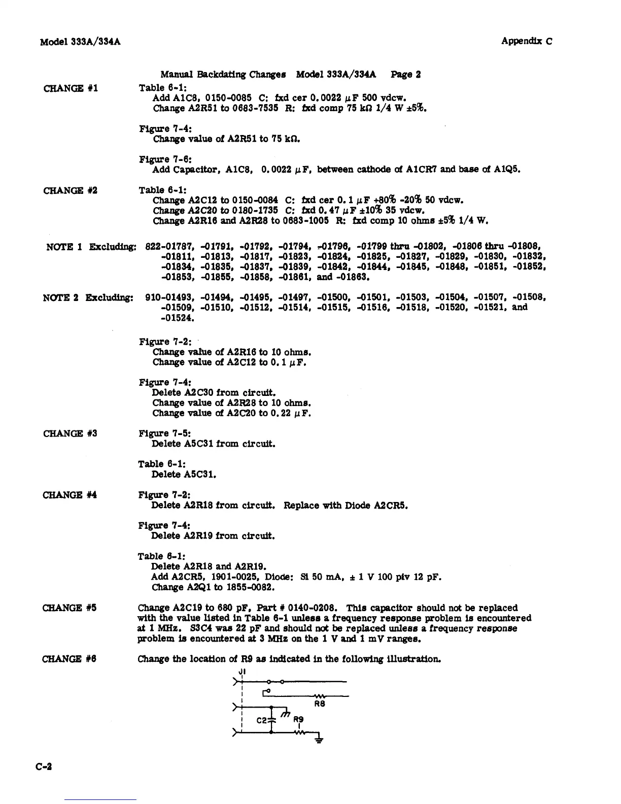
CHANGE
#6
Figure
7-2:
Change value of A2Rl6
to
10
ohms.
Change value
of
A2C12
to
0.1 pF,
Delete A2C30 from circuit.
Change value of A2R28 to 10
ohms.
Change
value
of
A2C20
to
0.22 pF.
Delete A5C31 from circuit.
Figure
7-4:
Figure 7-5:
Table 6-1:
Delete A5C31.
Figure 7-2:
Figure 7-4:
Delete A2R18 from circuit. Replace with
Diode
A2CR5.
Delete A2R19 from circuit.
Table 6-1:
Delete A2R18
and
A2R19.
Change A2Q1
to
18554082.
Add A2CR5, 1901-0025,
Diode:
Si
50
mA,
&
1
V
100
PlV
12 PF.
Change A2C19
to
680
pF,
Part
#
0140-0208.
This
capacitor should
not
be
replaced
with the value listed
in
Table 6-1 unless
a
frequency response problem
ia
encountered
at
1
MHz. S3C4
was
22
pF and should
not
be
replaced unless a frequency response
problem
is
encountered
at
3
MHz
on
the
1
V
and
1
mV
ranges.
Change the location
of
It9
as
indicated
in
the
following
illustration.
J'
--
--
c-2