Model
5315A/B
General
Information
Table
1-
1.
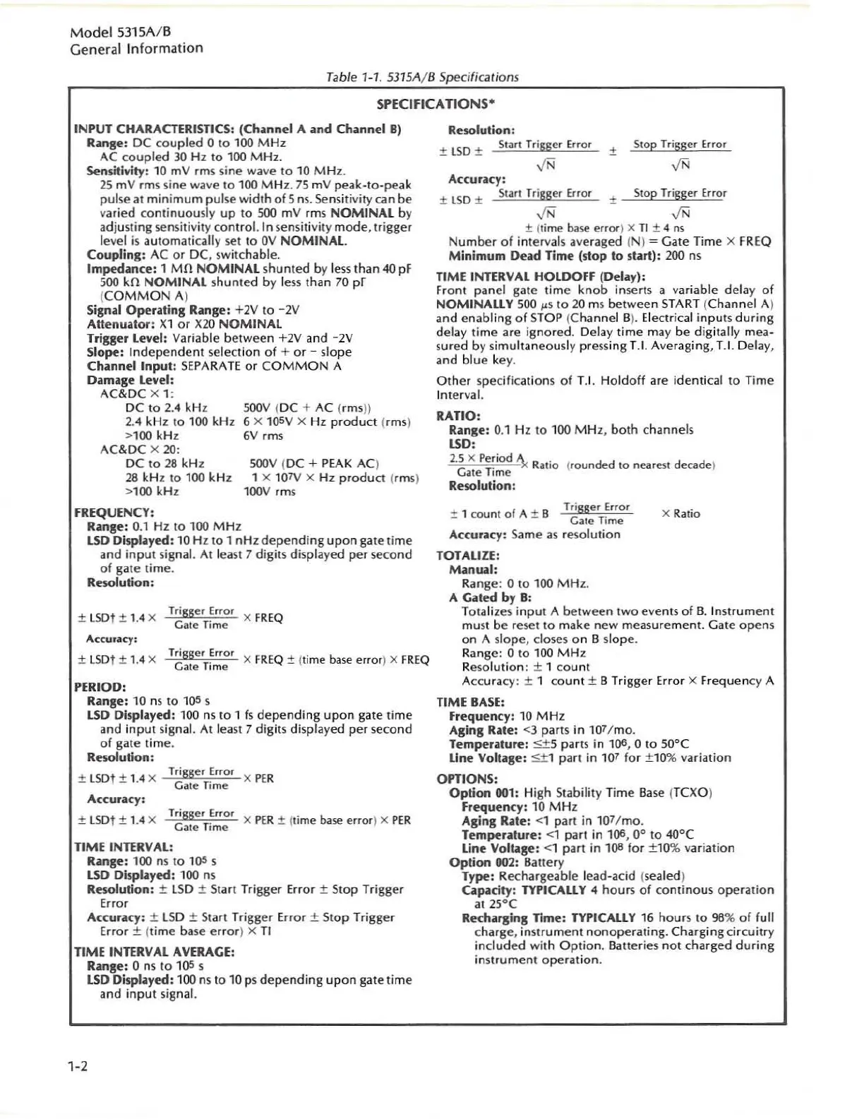
5315A
/ B Specifications
SPECIFICATIONS·
INPUT CHARACTERISTICS: (Ch
ol
nnel
A itnd Chitnnel 8)
Ritnge: DC
cou
pled 0
to
100
M Hz
AC coupled
JO
Hz
to
100
MHz.
Sensitiyity: 10 mV rms
si
ne wave
to
10
MHz.
25
mV
rm
s sine witve
to
1
00
M H
z.
75
mV peak-Io-peak
pul
se
al
min
imu
m
pul
se
w
idth
of
5
ns.
Se
nsitivity can be
varied continuously
up
to
500 mV
rm
s
NOMINAL
by
adjus
ting
sensitivity control. I n sensitivity mode, trigger
level
is
automati
ca
lly set
to
OV
NOMINAL
Coupling:
AC
or
DC,
sw
itchable.
Impedance: 1
Mn
NOMINAL
shunted by
les
s than
40
pF
500
kn
NOMINAL
shunted by l
ess
than
70
pr
(
COMMON
A)
Signal
Operitting
Range: +2V
to
-2V
Attenuator:
Xl
or
X20
NOMINAL
Trisser
lev
el
:
Var
iable between +2V and - 2V
Slope:
Ind
epend
ent
selec
tion
of
+ or - slo
pe
Channel
Input:
SEPARA
TE
or
COMM
ON
A
Damitge
level:
AC&DC X 1:
DC
to
2.4
kHz
2.4
kHz
to
100
kHz
>
100
kHz
AC&DC
X 20:
DC
to
28
kHz
28
kHz
to
100
kHz
>1
00
kHz
SOOV
(DC + AC (
rm
sl)
6
X
10SV
x Hz
product
(rms)
6V
rms
SOOV
(DC +
PEAK
AC)
1 X
107V
X Hz
product
(rms)
l00V
rms
FREQUENCY:
Rolnse: 0.1 Hz
to
100
MHz
LSD
Displityed:
10
Hz
to
1 nHz
de
p
ending
upon
gate
time
and
input
sig
na
l. At l
east
7 digits displayed per second
of
gate time.
Resolution:
+ LSOt + , 4 X Trigser Err
or
X
FREQ
-
_.
Cate Time
Accuracy:
± LSDt ± 1.4 X
Trigger Error
Gate Time
X
FR
EQ
± (
lime
b
ase
error
) x FR
EQ
PERIOD:
Range: 10
ns
to
lOS
s
LSD
Displolyed:
100
ns to 1
fs
depending
upon
gate
ti
me
and
inp
ut signal. At lea
st
7 digits
di
sp
la
yed per second
of
gate
tim
e.
Resolution:
+
LSD
t + 1 4 X Trigger Error x
PER
-
_.
Gale Time
AccurilCY:
±
LSD
t ± 1.4 X Trigser Error X
PER
± (
time
baM'
erro
r) x
PER
Gate T
ime
TIME
INnR
VAL:
Rolnse
: 1
00
ns
to
l
OS
s
LSD
Oisplilyed:
100
ns
Resolution: ±
LS
D ±
Sta
rt Trigger Error ± Stop Trigger
Error
AccuroilCY:
±
LSD
± Start Trigger
Err
or
± Stop Trigger
Error
± (t
im
e
base
e
rr
or
) X TI
TIME
INnRVAL
AV
ER
AGE:
1-2
Rolnse: 0
ns
to
l
OS
s
LSD
DispLiyed:
100
ns
to
10
ps
depending
upon
gate time
and
input
signal.
Resolution:
:t
LSD
±
Stilr(
Tr
igger ErrOl
±
S
top
Trigger Error
,fN
,fN
Acc
ur
uy:
±
LSD
:t
Star
l Trigger Error
::!:
SlOp
Trigger Error
± (
time
baM' error) x TI
:t
4
ns
Number
of
intervals averaged (N ) = Gate Time x
FR
EQ
Minimum
Dead Time (stop
to
stolrt):
200
ns
TIME
INTER
VAL HOLDOFF (De
loil
Y
):
Fronl panel gate time k
nob
inserts a variable
de
l
ay
of
NOMINALLY
SOO
~s
to
20
ms between START (Channel A)
and enabling
of
STOP
(Channel 5
).
Electrical in
pu
ts
during
delay time are
ignore
d. Del
ay
t
ime
may
be
dig
itally mea·
su
r
ed
by simultan
eo
usly pre
ss
ing
1.1
. Averaging, T.I. Delay,
and
blue
key.
Other
specifications
of
T.
r.
Hold
off
are identic
al
to
Time
Interval.
RATIO:
Rilnge:
0.1 Hz
to
1
00
M H
z,
both
channels
LSD:
2.5
)(
Period
A .
G
T
·
~x
RatiO
(
rounded
10
nearest decade)
ate
Ime
Resolution:
:t
1
cou
nt
of
A
:t
B Trigger E
rror
Gale T
ime
Acc
ufu
y:
Same
as
resolution
TOTALIZ
E:
Manual:
Range : 0
to
100
MHz.
A Gated by
B:
X Ratio
Totalizes
input
A between
two
eve
nt
s
of
B.
Instrument
mu
st be reset
to
make
new
measurement. Gate opens
on
A slope, closes
on
B
sl
ope
.
Range:
0
to
100
MHz
Resol
ution
: ± 1
co
unt
Accuracy: ± 1
co
unt
± B Trigger E
rro
r X Frequency A
TIME
BASE
:
Frequenc
y:
10
M
Hz:
Aging
Roilte
: <3 parts in
10
7/mo.
Temperature:
<+
5 parts
in
lOS,
0 to 50"C
Line Voltage:
$±
1 part in 1
07
for ±1
0%
variation
OPTIONS:
Option
001:
High Stabili
ty
T
ime
Base
(
TC
XO)
Frequenc
y:
10
MHz
Aging
Rolte
: <1 part in
107
/
mo
.
Temperolture:
<1 part
in
1()6,
0°
to 40°C
Line
Vo
ltase: <1 part
in
1()8
for
±
1()';l(,
vari
at
io
n
Option
002:
Sanery
Type: Rechargeable lead-acid (sealed)
Capaci
ty:
TYPICALLY 4 hours
of
co
ntin
ous
operation
oilt
25
°C
Rec::hilrging
nme:
TYPICALLY
16
ho
urs
to
98
%
of
full
charge, instrument nonopera
tin
g.
Charging circuitry
includ
ed with
Option.
Batteries
not
charged
during
ins
tr
ument
operation.