Model 5315A/B
Adjustments
5-2
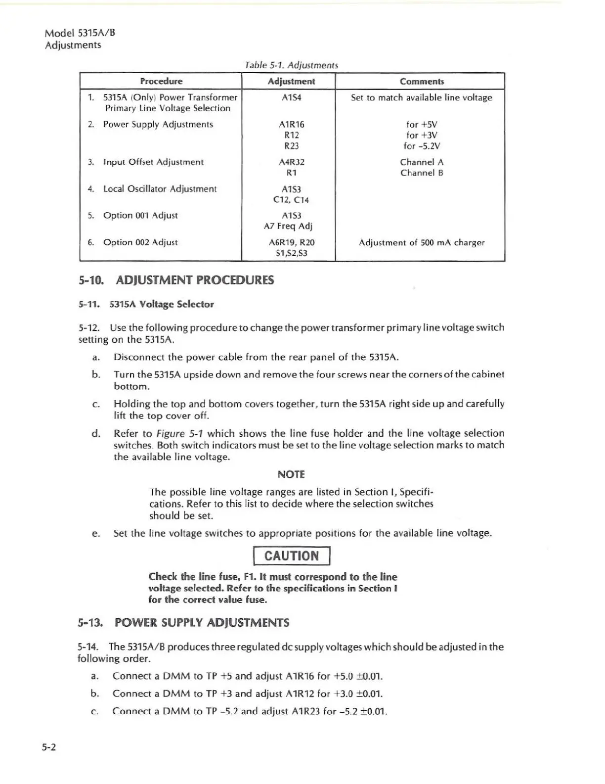
Table 5 1 Adjustments
-
Proccedure Adjustment
Comments
1.
53
1
5A
(Only) Power Transformer
A154
Set to match available line voltage
Primary
lin
e
Vo
ltage Selection
2.
P
owe
r Supply Adjustments
A1R
16 for
+5
V
<"
for
+3V
<23
for -5.2V
3. Input Off5et Adjustment
A4R32
Channe
l A
<1
Channel B
4.
local
Oscillator Adjustment
Al53
el2
,
04
5.
Option
001
Adjust
A1
53
A7
Fr
eq
Adj
6.
Opt
ion
002
Adjust
A6
R1
9,
R
20
Adjust
ment
of
500
rnA
charg
er
51,52
,5
3
5-10. ADJUSTME
NT
PROCEDURES
.>-11.
5315A
Volt~ge
Selector
5-1
2.
Us
e t
he
fo
ll
owing
procedu
re
to
change the power transform
er
primary l
in
e voltage
sw
it
ch
setting
on
the
53
l
5A.
a.
D
is
c
on
n
ec
t the
powe
r cable from the rear
pane
l of the 53l 5
A.
b.
Turn the
53
1
5A
upsi
de
down and r
emove
the
fo
ur
sc
rews near t
he
co
rners of t
he
cabin
et
bottom.
e.
Holding
the
t
op
and
botto
m covers together. turn the
531SA
ri
ght si
de
up and carefu
ll
y
li
ft
t
he
top
cover off.
d. Re
fe
r to Figure 5-1 which shows the line fuse holder and t
he
l
in
e voltage select
io
n
switches. Both switch
in
dicators must
be
set to the l
in
e v
ol
tage selection marks to match
the
ava
il
ab
le line voltage.
NOTE
T
he
poss
ibl
e line v
ol
ta
ge
ranges are
lis
ted
in
Section I, Specifi-
cation
s.
Refer to this
list
to decide where the selection
sw
it
ches
shou
ld
be
set.
e.
Set the line voltage
swi
tches
to
appropriate positions
fo
r t
he
ava
il
able line voltage.
I CAUTION I
Check
the
line fuse, Fl.
It
must
correspond
to
the
line
volt~ge
selected.
Refer
to
the
specifications in
Section
I
for
the
coned
value fuse.
5-13. POWER
SUPPLY
ADJUSTMENTS
5-
1
4.
The 53l5A/ 8 produces th
ree
r
egu
lated d
cs
upplyvoltages which shou
ld
beadj
usted
in
the
follow
in
g order.
a.
Connect a OMM to
TP
+5 and adjust
A1
R1
6 for +5.0
±O.D1
.
b. Conn
ec
t a DMM to
TP
+3 and adjust A
1R
12
fo
r +3.0 ±a.Ol .
e.
C
onn
ect a DMM to TP -5.2
and
adju
st
A1
R23
for -5.2 ±0.
01
.