Model
5315A
/ B
Servi
ce
8-58. The amplifier assembly provides separate low and high frequency buffer
amp
li
fiers.
The
low frequency path is
thro
ugh a dual-FET
totem-pole
configuration made
up
of Q4A
and
Band
a
ss
ociated
compon
ents.
R32
allows a slight offset adju
stme
nt
to
bal
ance
the
circuit. The high
f
requen
cy
buff
er
amp
li
fier, comprised
of
C8, C1
2,
C
18
,
R14,
R15
,
R16,
an Q3,
is
a simple ac-
co
upled, emitter-follower with
dc
bias
in
g.
It
s
output
is
combined
with
the
l
ow
frequen
cy
amplifier and
app
li
ed
to
one
side
of
comparator
U2.
The
dc
level from the Trigger
leve
l
co
ntrol
is
applied
to
t
he
other input. The
complementa
ry ECl
outputs
of
th
e comparat
or
are
input
to
a
differential amplifier, within transistor array Ul.
Th
e differential amplifier serves
to
level shift
the
Channel
A sign
al
,
before
routing
it
to
the
MRC.
Th
e MRC requires a uniq
ue
logic l
eve
l
of
<><+
2.4
(logic lowl,
to
+3.0 vo
lt
s (
logic
high).
8
-59
. An additional differential pair, within
U3,
form a
one-
shot. This circuit monitors
the
complementary
output
of
U2
,
and
drives the Trigger
light
on
A3.
CR
1
keeps
U3
from going into
saturation, which allows
it
to
capture
narrow pulses from
the
co
mp
arato
r.
8-60. OPTIONS THEORY (OPTIONS
002
AND
001)
8-61.
A6
BaHery
Ch.uger
Assembly
Option
002
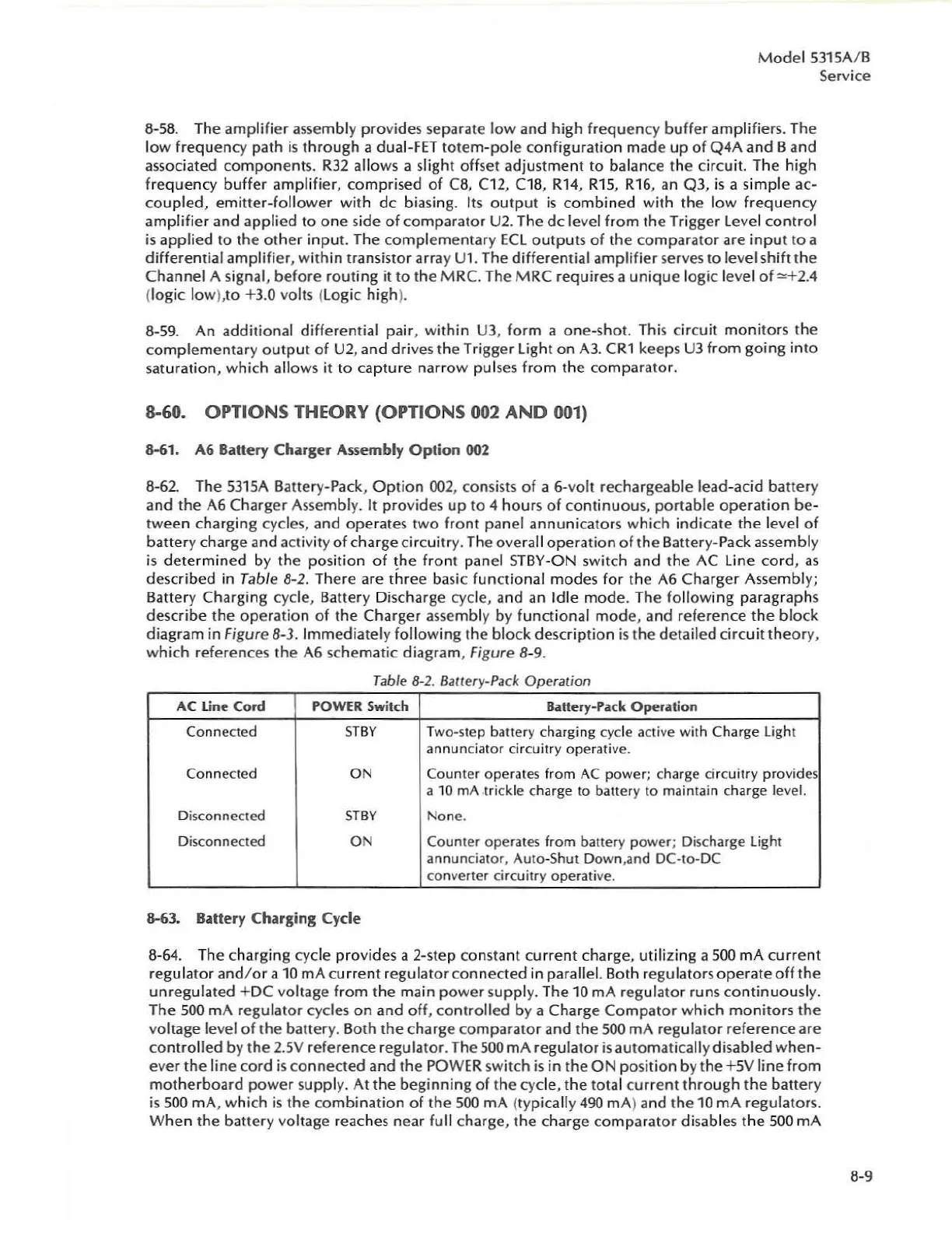
8-62. The
531
5A
Battery-Pack,
Option
002
,
co
nsists
of
a 6-volt r
ech
arg
ea
ble lead-acid batte
ry
and
the
A6
Charger Assembly.
It
provides
up
to
4 h
ours
of c
ontinuou
s,
portab
le
operation
be-
tween
charging cycles, and
operates
two
front panel annunicat
or
s w
hi
ch indicate
the
level of
batter
y charge and activity of
charge
circuitr
y.
Th
e
ove
ra
ll
opera
tion
of
t
he
Battery-Pack a
ssemb
ly
is
de
t
ermined
by
the
po
sition
of
~he
front panel S
TBY-ON
switch
and
the
AC
line
cord,
as
describ
ed
in Table 8-2.
Th
ere
are
three
basic functional
modes
for
the
A6
Charge
r Assembl
y;
Battery Charging
cy
cl
e,
Battery
Di
scharge
cy
cle, and an Idle
mo
de. The following paragraphs
describe
the
op
eratio n of
the
C
har
ger assembly by functi
ona
l
mod
e,
and r
efer
ence
the
blo
ck
diag
ra
m
in
Figure 8-3. Immediately following the block description
is
the detailed circuit
theor
y,
which re
fe
rences the
A6
schematic diagram, Figure 8-9.
Tab
le 8-2. Bauery-Pack Operation
AC
Line
Cord
POWER Switch
!bitely-Pull:
Oper.il.tion
Connected
S
TBY
T
wo-
step battery charging cycle active
with
Charge Light
annunciator
circui
tr
y
operativ
e.
Conne
cted
ON
Counter
ope
rat
es
from
AC
po
wer;
charge ci rc
uitry
pro
vides
a
10 rnA .
trickle
charge
to
battery to maintain charge le
ve
l.
Disconnected S
TBY
None
.
Disconnected ON Cou
nte
r
ope
rat
es
fr
om
battery
power
; Discharge
li
ght
an
nu
nciator,
Auto
-Shut
Down
,and
DC-Io-DC
co
n
ve
rter
circuit
ry operative.
8-63. Battery Charging Cycle
8-64. The char
gi
ng cycle provides a 2·step c
on
stant current
charge
, utilizing a 500 mA
current
r
egu
lator and/
or
a
10
mA cu rr
ent
r
eg
ul
ator
connected
in pa
ra
ll
el. Both regulators
operate
off
the
unregulated
+
DC
voltage from
the
main p
owe
r
su
ppl
y.
T
he
10
mA
regulator runs
con
ti
nuo
usl
y.
The
500
mA regulat
or
cycles
on
and
off, c
on
trolled by a
Charge
C
ompat
or which
mo
nitors
the
voltage level
of
the
battery. Both
the
charge
compa
rator and
the
SOO
mA
r
eg
ul
ator
reference
are
contro
lled by
th
e
2.5V
r
efere
nce
regulator.
Th
e
500
mA regulator is automatically disa
bled
when-
ever
the
line
cord
is
c
onnected
and
the
POWER
switch
is
in t
he
ON
po
si
ti
on by t
he
+
5V
line from
motherboard
power
s
upp
l
y.
At
the
beginning of the cycle, the
to
tal curr
en
t
through
the
battery
is
500
mA
, which is the
co
mbinati
on
of
th
e
500
mA
(typically 490
rnA
)
and
the
10 mA regulators.
W
hen
the battery
vol
tage reac
he
s
nea
r f
ull
charge,
the
charge
co
mparator
disables
the
500
rnA
B·9