SVC 4-31
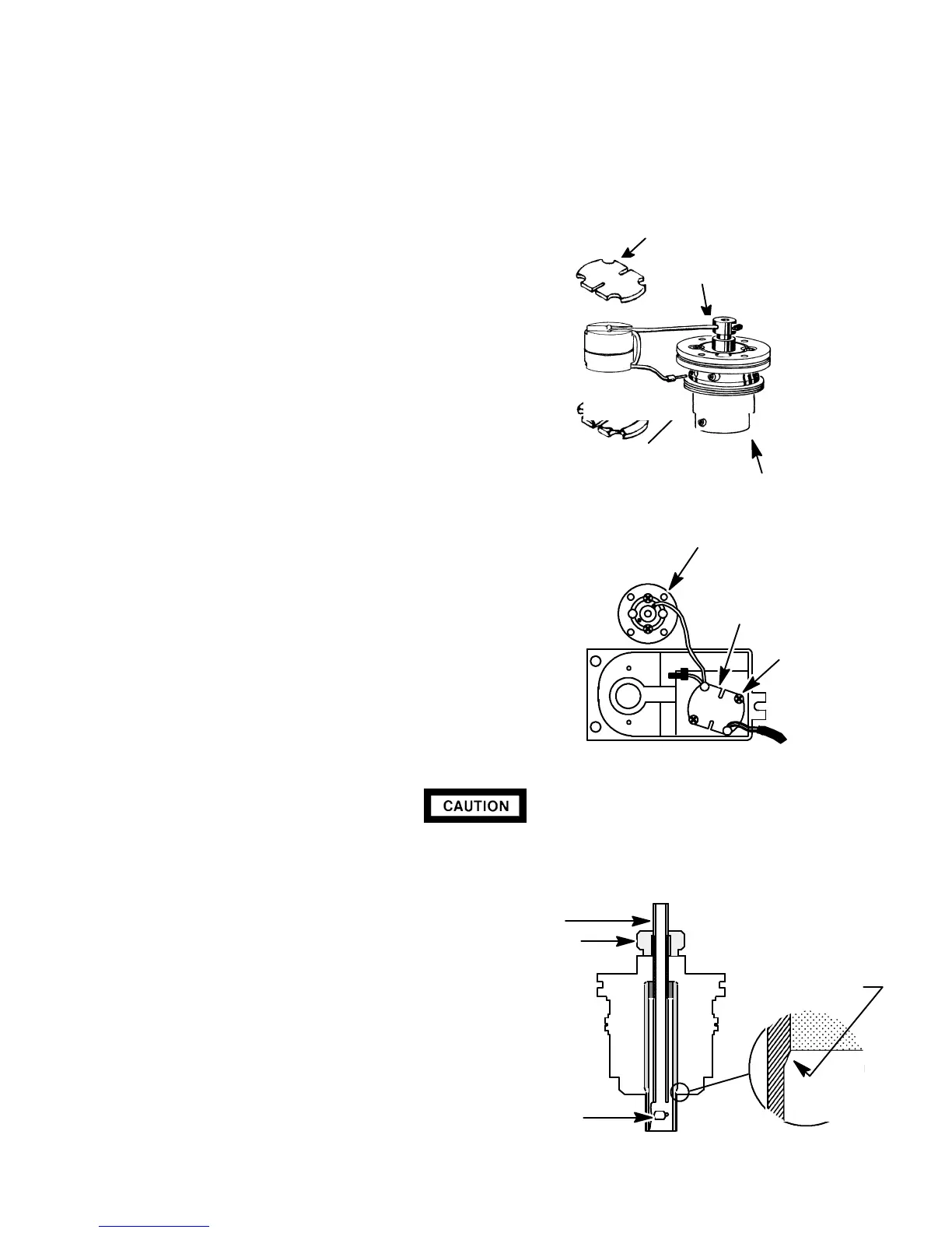
17. Remove the collector assembly and the toroid
spacer assembly from the detector cover, as a
unit.
18. Using a 1.5-mm hex wrench, loosen the set
screw securing the lower toroid lead to the col-
lector assembly.
19. Remove the lower toroid lead from the collector
assembly.
20. Desolder the soldered toroid lead from the up-
per portion of the collector assembly.
21. Remove the upper toroid lead from the collector
assembly.
22. Install the new toroid leads to the collector as-
sembly.
23. Tighten the setscrew securing the lower toroid
wire to the collector assembly, snugly.
24. Solder the upper toroid lead to the collector
assembly.
25. Install the new toroid/spacer assembly in the
detector cover and secure with two screws.
26. Thread the bead power cable through the
notch in the end of the detector cover, making
sure that only the heat-shrink tubing, not the
bare wire, contacts the cover.
27. Secure the collector assembly to the detector
cover using two Pozidriv screws.
Do not handle the collector with bare hands. Use needle-nose pliers when handling
the collector to avoid contaminating it with finger oils and/or other contaminants.
28. Use needle-node pliers to install the collector
into the collector assembly, from the bottom.
29. Align the collector to the collector assembly
in accordance with the illustration below.
30. When properly aligned, secure the collector
inside the collector assembly by tightening two
set screws.
31. Place the detector cover over the detector base
and secure it with the three screws previously
removed.
SPACER
TOROID WIRE
SOLDERED AT THIS
POINT
SET SCREW
COLLECTOR
ASSEMBLY
SCREW
TOROID
SPACER
ASSEMBLY
COLLECTOR
ASSEMBLY
COLLECTOR
BODY
NOTE POSITION
OF COLLECTOR
NPD ACTIVE
ELEMENT
NPD COLLAR
NPD COLLECTOR ASSEMBLY
Artisan Scientific - Quality Instrumentation ... Guaranteed | (888) 88-SOURCE | www.artisan-scientific.com

 Loading...


