SVC 5-5
16. Disconnect connector P7 from its receptacle on
the main PCB by pulling it straight off. (Heated
zones corresponding to sensor lead locations
are labeled to the right of the P7 connector re-
ceptacle on the main PCB.)
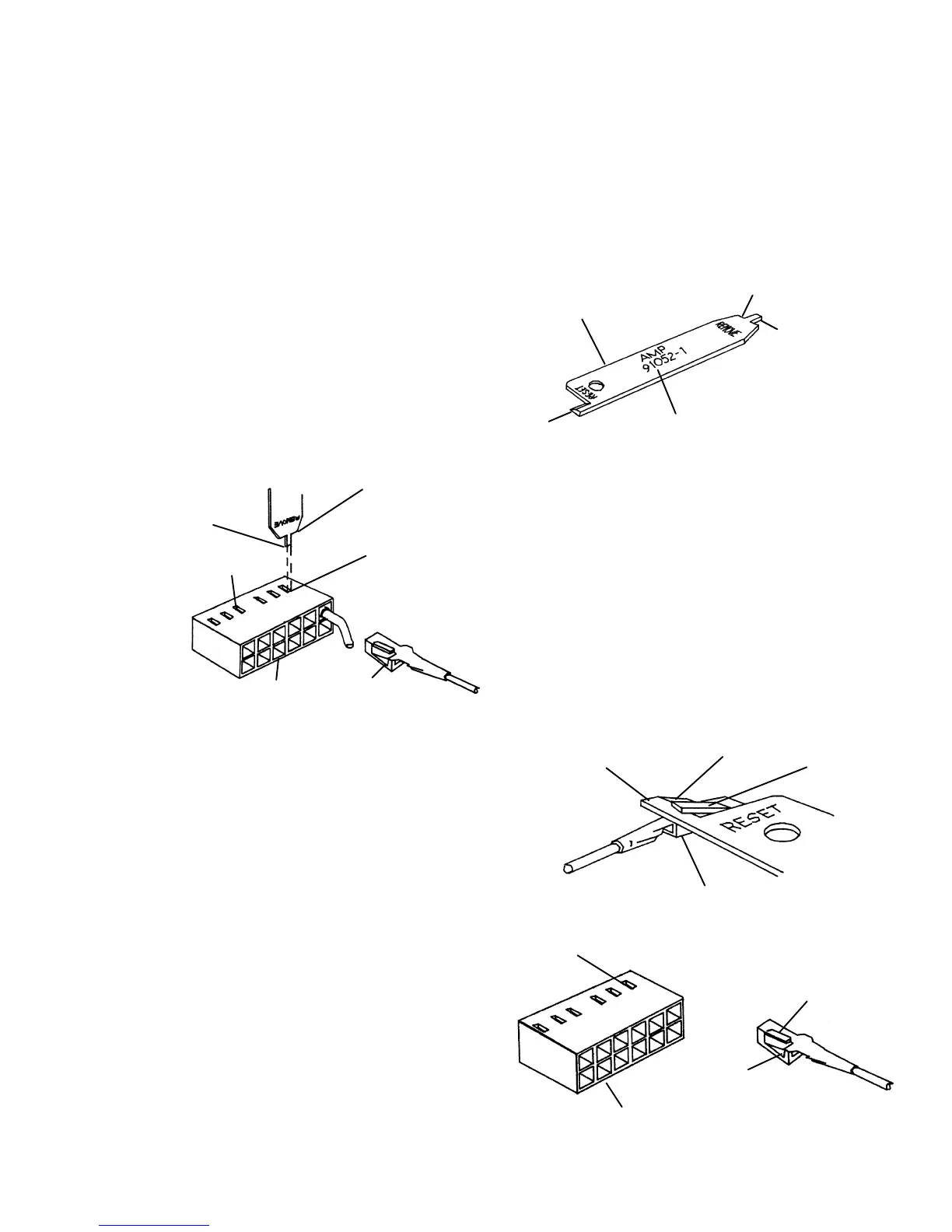
17. Use the lance release tip of an AMP pin extrac-
tion/lance reset tool (8710-1542) to remove the
appropriate pins from connector P7. (The tool
features a lance release tip and a lance reset
tip. The lance release tip is used to depress
the pin locking lance to extract the pin from a
connector. The lance reset tip positions a lock-
ing lance to its proper height to ensure reten-
tion of the pin in the connector.)
18. From inside the oven, draw the sensor leads
through the opening in the rear of the oven.
19. Prepare the pins corresponding to the sensor
cartridge of the replacement shroud by adjust-
ing their locking lances using the lance reset
portion of the tool.
20. Feed the sensor cartridge pins through the
opening in the oven and ready them for installa-
tion into the main board connector shell.
21. Insert the pins for the replacement sensor into
their appropriate locations in the plug, making
sure the locking lance on each pin seats into its
hole through the side of the plug.
22. Gently pull on the wire to ensure that the pin is
locked in the connector.
EXTRACTION
LANCE RESET
TOOL
LANCE
RELEASE
TIP
TOOL
STOP
DASH NUMBER
MARKED HERE
LANCE
RESET TIP
TOOL STOP
INSERT TIP
HERE
(BACK OF
CAVITY)
LANCE
RELEASE
TIP
LOCKING
LANCE
CAVITY
BACK OF
HOUSING
CONTACT
(TYPICAL)
RECEPTACLE
BOX (TYPICAL)
LOCKING
LANCE
TAPER
LANCE
RESET
TIP
LOCKING
LANCE
CAVITY
LOCKING
LANCE
BACK OF
HOUSING
CONTACT
(TYPICAL)
Artisan Scientific - Quality Instrumentation ... Guaranteed | (888) 88-SOURCE | www.artisan-scientific.com
 Loading...


