SVC 8-3
Replace Display PCB Assembly
HAZARDOUS VOLTAGES ARE PRESENT IN
THE INSTRUMENT WHEN THE POWER CORD
IS CONNECTED. AVOID A POTENTIALLY
DANGEROUS SHOCK HAZARD BY
DISCONNECTING THE POWER CORD
BEFORE WORKING ON THE INSTRUMENT.
1. Set the main power line switch to the off position.
2. Disconnect the power cable from its receptacle.
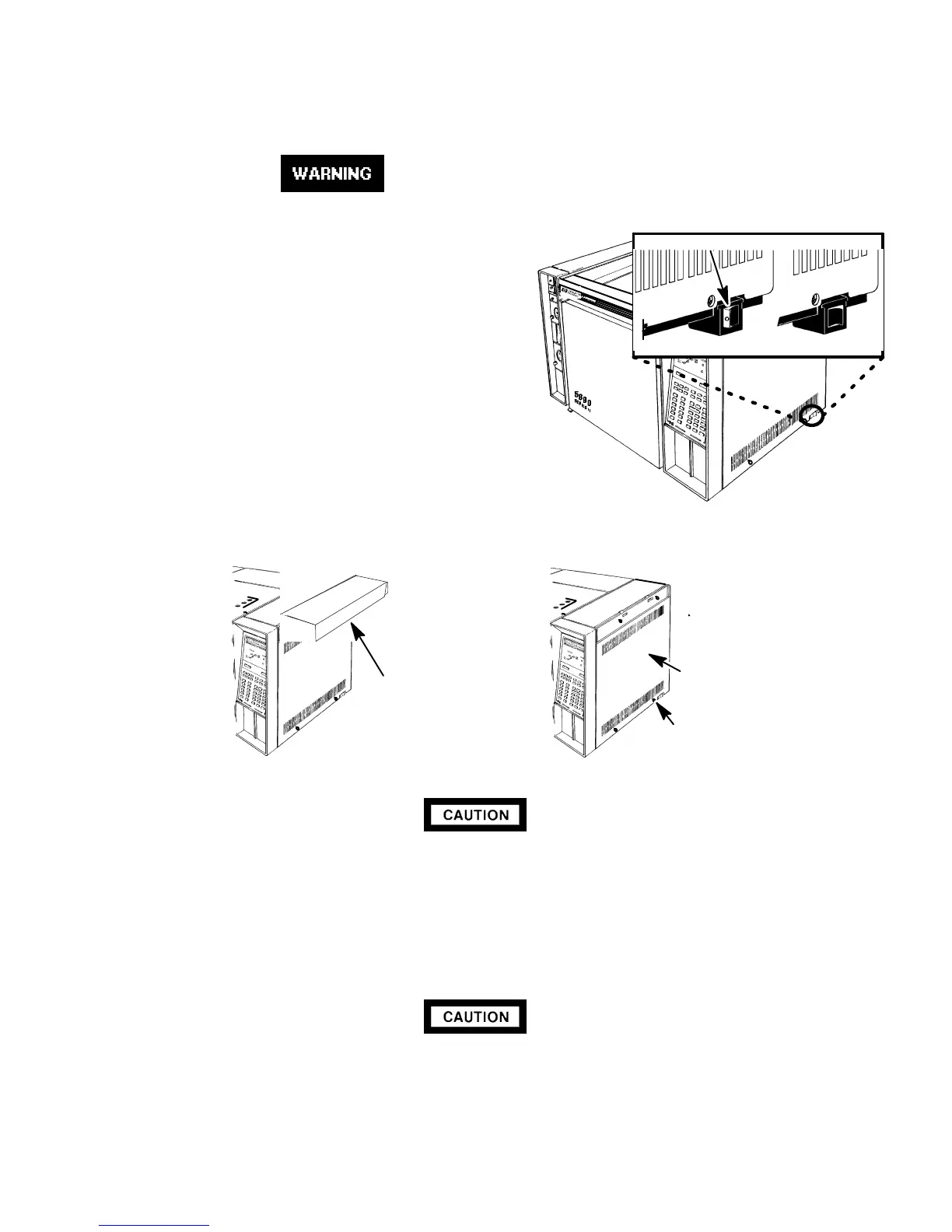
3. Remove the electronics carrier top cover by
grasping it at the rear and lifting upwards until
its catch releases, then pulling it towards the
rear of the instrument.
4. Remove the right side panel by removing four screws:
two each along its upper and lower edges.
This procedure requires precautions against ESD (Electro-Static Discharge). Use a
groundedwrist strap (part no. 9300-0969 - large, or9300-0970 - small) connected
to a suitable ground. Failure to heed this caution may result in damage to the
instrument.
5. Free the keyboard connector (J1) from connector receptacle P1 on the main PCB by releasing
the locking tabs (one on either side of the connector receptacle).
When disconnecting aplug, pull on the plug not on its wires. Pulling on the wires may
cause breakage.
6. Remove connector J1 from connector receptacle P1 by carefully pulling it straight out.
OFF ON
RED O VISIBLE
ELECTRONICS
CARRIER TOP
COVER
SCREWS
SCREWS
RIGHT SIDE
PANEL
Artisan Scientific - Quality Instrumentation ... Guaranteed | (888) 88-SOURCE | www.artisan-scientific.com

 Loading...


