SVC 9-6
12. Verify all interconnecting plugs are now disconnected.
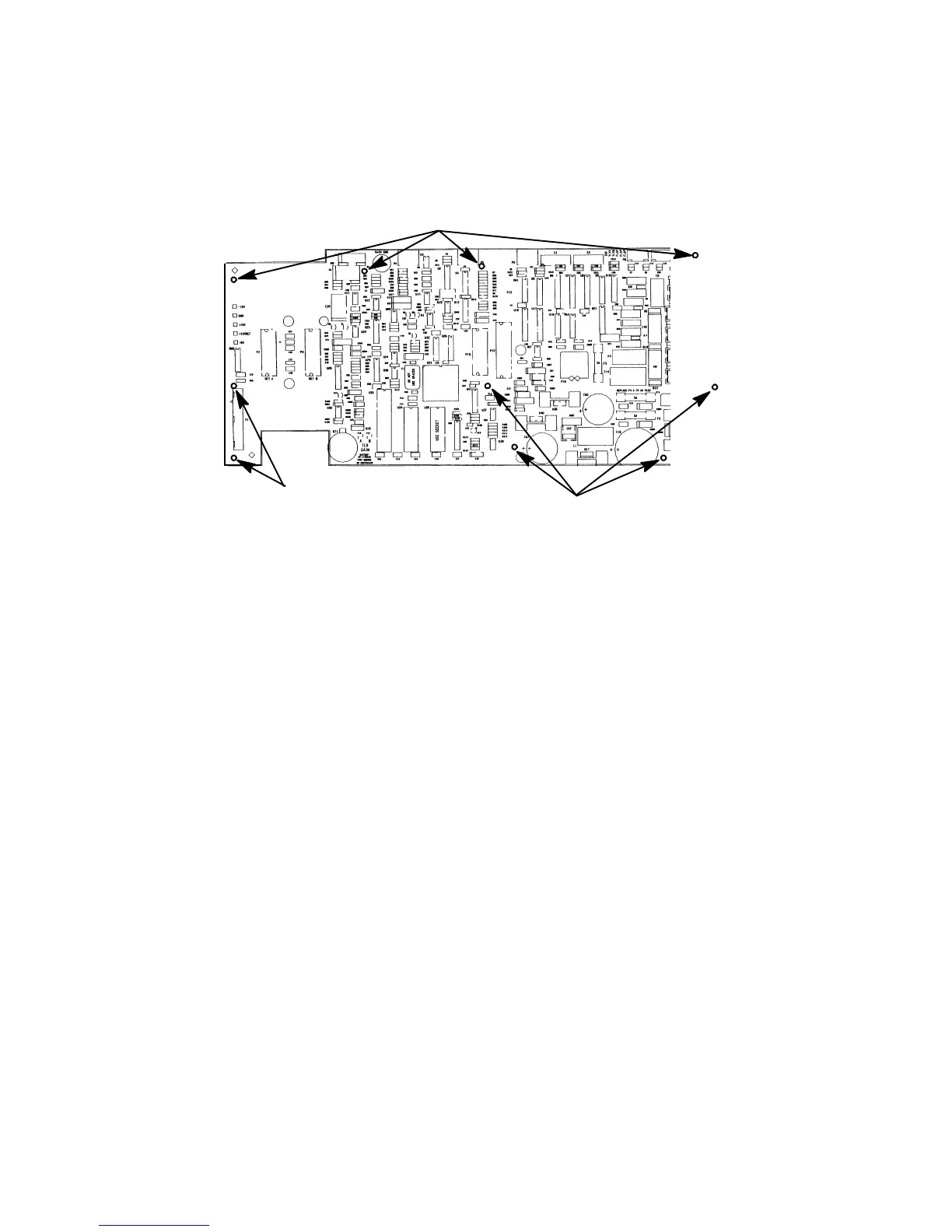
MOUNTING HOLES
MOUNTING HOLES
MOUNTING HOLES
13. Remove seven screws securing the main PCB to the electronics flow carrier.
14. Remove the main PCB from the instrument by carefully tipping it towards the right side of the
instrument, and then lifting it from its support brackets.
15. Position the replacement main PCB so its lower edge is within the support brackets; then slide
the board to its left or right as needed to align it with locater posts and holes for mounting
screws.
16. Secure the board in place with the seven mounting screws. Make sure the longest screw is
installed in the hole marked “MAIN GND” at the top of the board.
17. Install all connectors, detector PCBs, communications interface PCB (if present), EPC/MPC in-
terface PCB (if present), and signal cables.
18. Restore all gas supplies to the instrument.
19. Install the right side panel and secure using four screws.
20. Install the electronics carrier top cover.
21. Restore power to the HP 5890 Series II.
Artisan Scientific - Quality Instrumentation ... Guaranteed | (888) 88-SOURCE | www.artisan-scientific.com

 Loading...


