SVC 10-3
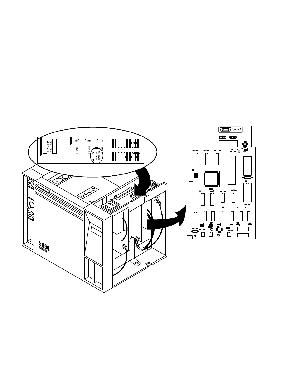
8. If an HPIB/RS-232-C communications PCB is installed, free and remove the rear panel PCB
cable from the connector on the communications PCB by releasing the locking tabs (one on
either side of the connector receptacle) and pulling the cable straight out.
9. If an RS-232-C communications PCB is installed, a different cable is used to connect the PCB
to the RS-232-C port of the connected device. Remove the 12-pin connector from the com-
munications PCB. (The cable is installed through the opening where the INET cables are usual-
ly connected.)
10. If an analog input communications PCB in installed, remove the cable connected to at the top
of the PCB.
11. Remove the communications PCB by grasping it in the center area along its right edge and
pulling it from its connector on the main PCB.
COMMUNICATIONS INTERFACE
PCB (TYPICAL)
Artisan Scientific - Quality Instrumentation ... Guaranteed | (888) 88-SOURCE | www.artisan-scientific.com

 Loading...


