SVC 10-4
12. Install the replacement PCB by inserting it straight into its connector on the main PCB.
13. Connect the cable(s) removed during steps 7 through 10.
14. Install the right side panel and secure using four screws.
15. Install the electronics carrier top cover.
16. Restore all gas supplies.
17. Restore power to the instrument.
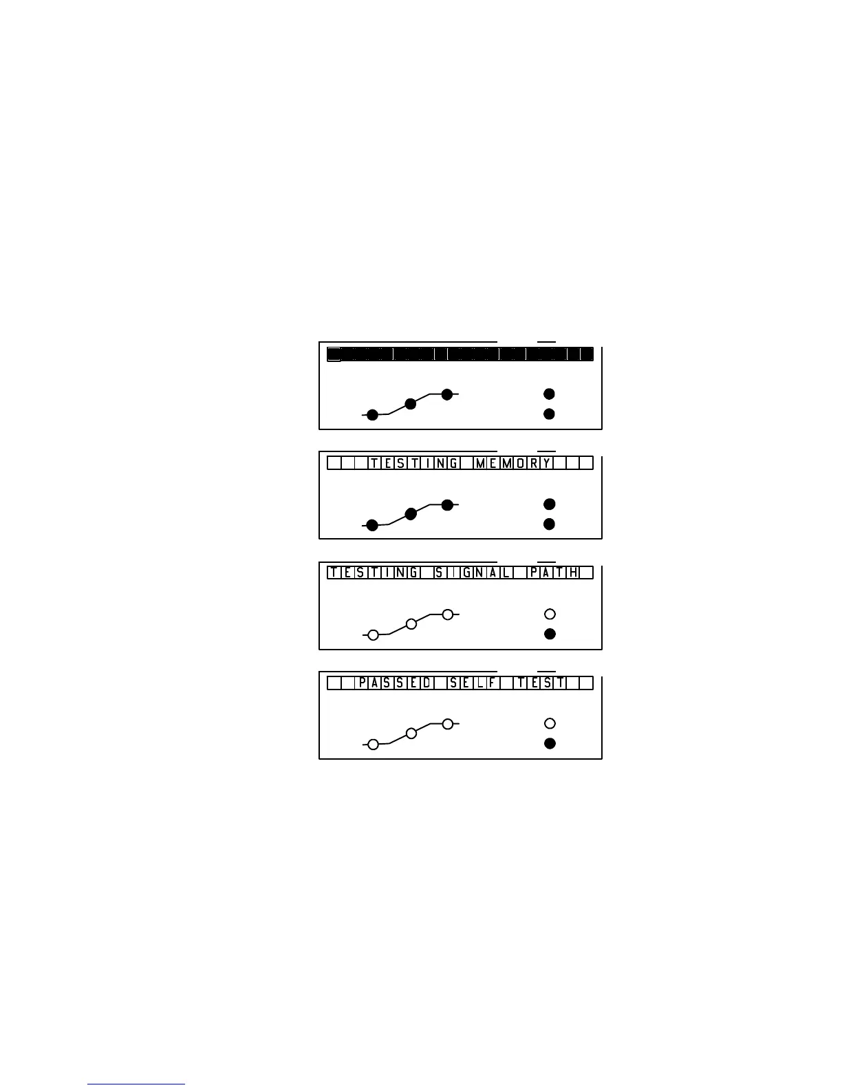
18. Observe the alphanu-
meric display, as the in-
strument performs an
internal self-diagnostic
integrity check. to en-
sure that the instrument
shows the expected
normal displays.
OVEN
STATUS
RUN
NOT
READY
FINAL
TIME
RATE
INITIAL
TIME
OVEN
STATUS
RUN
NOT
READY
FINAL
TIME
RATE
INITIAL
TIME
OVEN
STATUS
RUN
NOT
READY
FI-
NAL
TIME
RATE
INITIAL
TIME
OVEN
STATUS
RUN
NOT
READY
FINAL
TIME
RATE
INITIAL
TIME
ACTUAL SETPOINT
ACTUAL
ACTUAL
ACTUAL
SETPOINT
SETPOINT
SETPOINT
Test of display elements:
all alphanumeric and LED
elements are lit.
5890 Series II memory test
in progress.
5890A Self-testing in
progress.
LEDs off, except possibly
“NOT READY.”
Message indicating normal
termination of diagnostic
tests after power restoration.
User setpoints remain in
force.
LEDs off, except possibly
“NOT READY.”
NORMAL“INTEGRITY CHECK”
AT POWER-ON
Artisan Scientific - Quality Instrumentation ... Guaranteed | (888) 88-SOURCE | www.artisan-scientific.com

 Loading...


