SVC 11-7
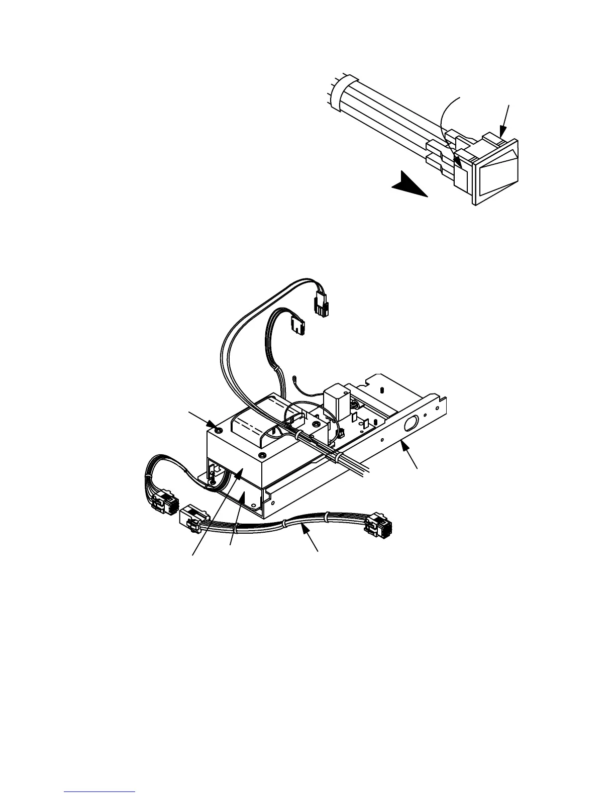
11. At the right side of the instrument, below the
main PCB, remove the power switch from its
slot by prying the plastic locking tabs on each
side of the switch in toward the switch body.
12. Remove the four push-on-type connectors
from the rear of the switch.
13. Remove the three nuts and one screw securing
the transformer bracket to the AC power supply
base.
14. Slowly lift the transformer and transformer
bracket off of the AC power supply base as a
unit, being careful not to strain the wiring from
connector P10 and the power switch.
AC POWER
SUPPLY BASE
EXTENSION
CABLE FOR
UPGRADED
SERIES I
TRANSFORMER
BRACKET
TRANSFORMER
SCREW, INSULATOR
BUSHING
POWER SUPPLY ASSEMBLY SHOWN REMOVED
FROM INSTRUMENT FOR CLARITY
15. Free the wiring from connector P10 and the power switch from their associated paths in the
electronics carrier.
16. Remove the transformer and transformer bracket from the rear of the instrument, as a unit.
17. Remove the four screws and four insulator bushing which secure the transformer to the trans-
former bracket.
PRESS HERE
PULL OUT OF
INSTRUMENT
Artisan Scientific - Quality Instrumentation ... Guaranteed | (888) 88-SOURCE | www.artisan-scientific.com
 Loading...


