The pulsed-RF network analyzer system allo ws you to select either the normal precision 10
kHz IF bandwidth or the new wideband 3 MHz IF bandwidth. The wide IF and detection
bandwidth allows testing using pulses as short as 1 microsecond but with accuracy comparable
to traditional non-pulsed measurements.
These system comp onents may b e rack-mounted or arranged on a desktop.
Theory of Operation
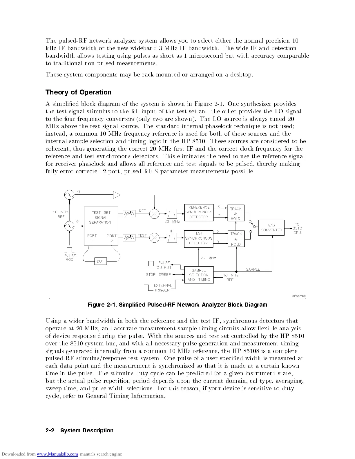
A simplied blo ck diagram of the system is shown in Figure 2-1. One synthesizer provides
the test signal stimulus to the RF input of the test set and the other provides the LO signal
to the four frequency converters (only two are shown). The LO source is always tuned 20
MHz ab ove the test signal source. The standard internal phaselo cktechnique is not used;
instead, a common 10 MHz frequency reference is used for b oth of these sources and the
internal sample selection and timing logic in the HP 8510. These sources are considered to be
coherent, thus generating the correct 20 MHz rst IF and the correct clo ck frequency for the
reference and test synchronous detectors. This eliminates the need to use the reference signal
for receiver phaselo ck and allows all reference and test signals to b e pulsed, therebymaking
fully error-corrected 2-p ort, pulsed-RF S-parameter measurements p ossible.
Figure 2-1. Simplified Pulsed-RF Network Analyzer Block Diagram
Using
a
wider
bandwidth
in
b
oth the
reference
and
the
test
IF,
sync
hronous
detectors
that
op
erate
at
20
MHz,
and
accurate
measuremen
t
sample
timing
circuits
allow
exible
analysis
of device resp onse during the
pulse. With the sources and test set con
trolled b
y the HP 8510
over the 8510 system bus, and with all necessary pulse generation and measuremen
t timing
signals generated in
ternally from a common
10 MHz reference, the HP 85108 is a complete
pulsed-RF stimulus/resp onse test system. One pulse of a
user-specied width is measured at
each data p oin
t and the measuremen
t is sync
hronized so that it is made at a certain kno
wn
time in the pulse. The stimulus duty cycle can b e predicted for a given instrument state,
but the actual pulse rep etition p erio d depends upon the current domain, cal typ e, averaging,
sw
eep
time,
and
pulse
width
selections.
F
or
this reason,
if
y
our
device
is
sensitiv
e
to
dut
y
cycle,
refer
to General
Timing
Information.
2-2
System
Description