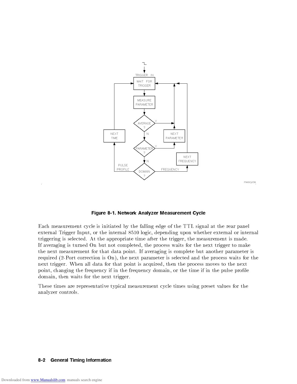
Figure
8-1.
Netw
ork
Analyzer
Measurement
Cycle
Eac
h
measuremen
t
cycle is
initiated b
ythe
falling edge
of
the
TTL
signal
at
the
rear
panel
external
Trigger
Input, or
the
in
ternal
8510
logic,
dep
ending
up
on
whether
external
or
in
ternal
triggering is selected. At the appropriate time after the trigger, the measurement is made.
If averaging is turned On but not completed, the pro cess waits for the next trigger to make
the next measurement for that data point. If averaging is complete but another parameter is
required (2-Port correction is On), the next parameter is selected and the pro cess waits for the
next
trigger.
When
all
data
for
that
p
oin
t
is acquired,
then
the
pro
cess
mo
v
es
to
the
next
p
oin
t,
changing
the
frequency
if
in
the
frequency
domain,
or
the
time
if
in the
pulse
prole
domain,
then
w
aits
for
the
next
trigger.
These times are represen
tative t
ypical measuremen
t cycle times using preset v
alues for the
analyzer con
trols.
8-2
General
Timing
Information