Theory
of
Operation 2-11
The
makeup
of the
ID
and
data
fields
is
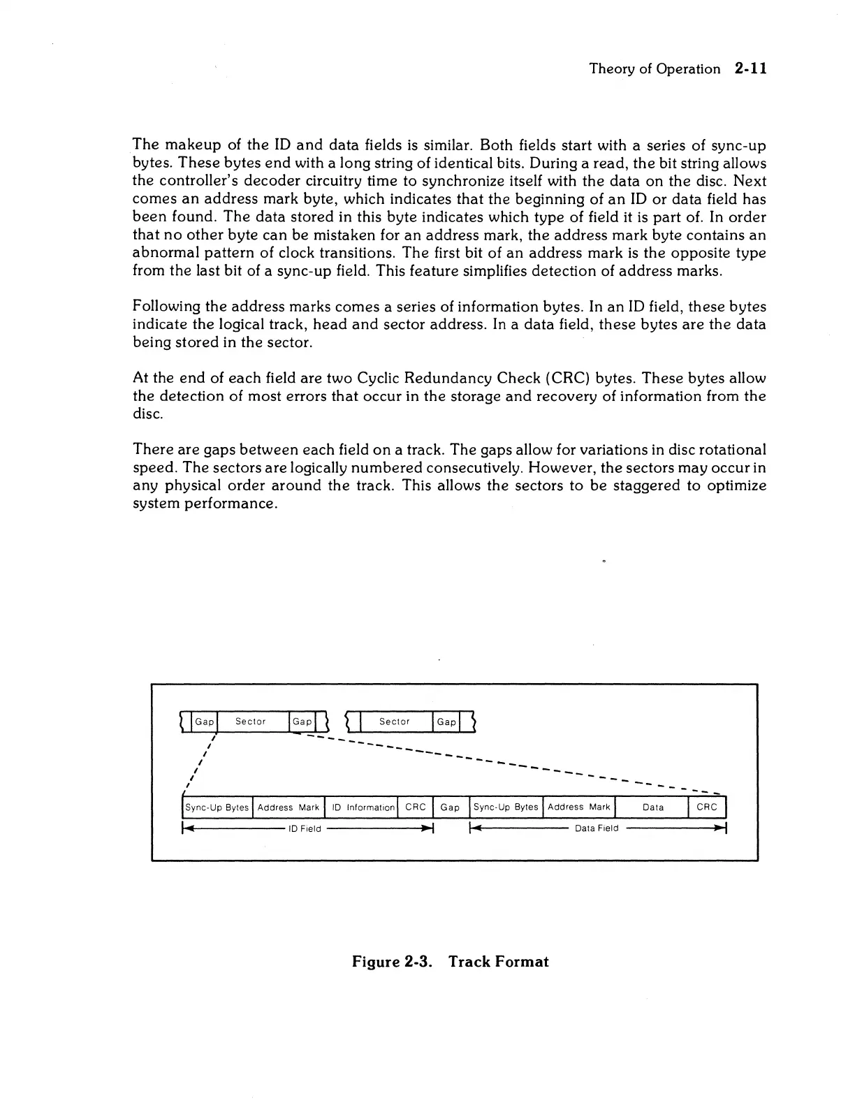
similar. Both fields start with a series of sync-up
bytes.
These
bytes
end
with a long string of identical bits. During a read,
the
bit string allows
the controller's
decoder
circuitry time to synchronize itself with
the
data
on the disc. Next
comes
an
address mark byte, which indicates
that
the beginning of
an
ID
or
data field has
been
found. The data stored in this byte indicates which type of field
it
is
part
of. In
order
that
no
other
byte can be mistaken for
an
address mark, the address mark byte contains
an
abnormal
pattern of clock transitions. The first bit of
an
address mark
is
the opposite type
from the last bit of a sync-up field. This feature simplifies detection of address marks.
Following the address marks comes a series of information bytes. In
an
ID
field, these bytes
indicate the logical track,
head
and
sector address.
In
a
data
field, these bytes
are
the data
being stored in the sector.
At
the
end
of
each
field are two Cyclic Redundancy Check (CRC) bytes. These bytes allow
the detection of most errors
that
occur in the storage
and
recovery of information from
the
disc.
There are gaps between each field
on
a track. The gaps allow for variations in disc rotational
speed. The sectors
are
logically
numbered
consecutively. However, the sectors may occur in
any physical
order
around
the track. This allows the sectors to be staggered to optimize
system performance.
t I
Gap
1
Sector
I Ga p I \ \ I
Sector
I
Gap
I
~
~~/~------~~-~-~----
I
---_
I
----
__
_
I
---
____
_
I
__
_
I -
__
, ---
..---------10
Field
------...-1
.....
---------
Data Field
------l~
Figure
2-3.
Track
Format
 Loading...