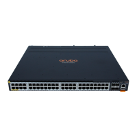
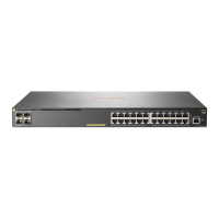
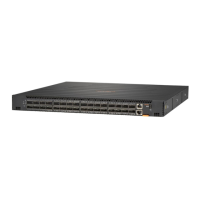
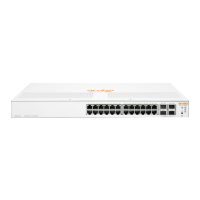
4 Line module status LEDs Indicates if a line module is installed in a line module slot (3
through 7 for 6405 switches; 3 through 12 on 6410
switches). If a line module is installed in a given slot, then
the numbered LED for that slot glows steady green.
5 Front Power supply status (1 2 3 4)
LEDs
Indicates if a power supply is installed in the slot. If an active
power supply is installed, then the LEDs glow steady green.
6 Fan tray status LEDs (1 - 4) Indicate if the fan tray is installed in the slot. If a fan tray is
installed in the slot, then the LED glows steady green.
7 LED mode: Usr1, Usr2 Spd, and PoE
LEDs
The display of these LEDs is based on the LED mode button
selection.
• Usr1 LED: Indicates if the line module is working
correctly.
• Usr2 LED: Reserved
• PoE: Indicates overall status of Power-over-Ethernet in
the system.
◦ O: disabled or not currently delivering power.
◦ On Green: Normal operation;
◦ Slow Flash Orange: PoE fault condition. Use line
module status LEDs and LED Mode to isolate the
failure down to the line module and port level.
• Spd LED: Indicates the trac rate of the line module.
8 Auxiliary port
Without a USB device installed, the auxiliary port LED is o
after power-on and self-test.
With a USB device installed, this LED displays the following
after power-on and self-test:
• Steady green: USB installed, initialized, and mounted, but
no data transfer.
• Flicker green: Data transfer in progress
9 Mgmt port (OOBM Port) with
Activity/Link LED
Without an active network connection, this LED is o after
power-on and self-test completes.
With an active network connection, this LED operates as
follows:
• Half-bright green: Port enabled and receiving Link
indication from connected device.
• Flickering half-bright to full-bright green: Varying port
activity level.
• Steady green: Port at high utilization.
10 Serial console port (RJ-45)
11 USB-C console port
Table Continued
Chapter 4 Introducing the Aruba 6400 switch series 25

 Loading...
