78 Chapter3
Remove/Replace System Components
Removing/Replacing System Components
System Area Fan Module Removal
To remove the fan module from the system area, follow this procedure:
1. Complete the procedure in the section “Removing the Front Bezel and Top Cover”
found in this chapter.
2. Complete the procedure in the section “Removing the Liquid Crystal Display”
found in this chapter.
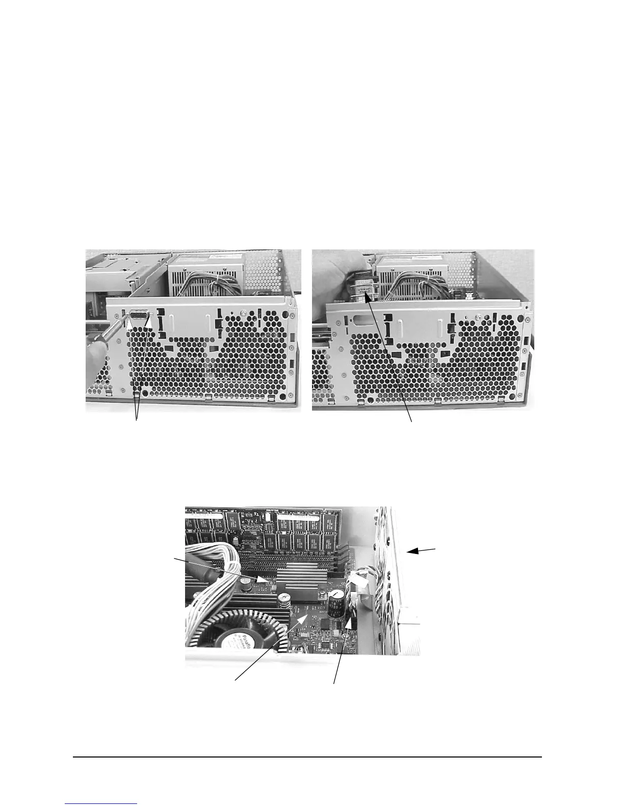
3. Unscrew the two LCD connector screws and remove the LCD connector from its
opening in the chassis. See Figure 3-62.
Figure 3-62. Removing the LCD Connector
4. Disconnect the two fan-module power cables in the system area from the system board.
See Figure 3-63.
Figure 3-63. Disconnecting the Fan-Module Power Cables for the System Area
LCD Connector Screws LCD Connector
Fan-Module Power Cables
Fan Module
System Board
System Area
 Loading...