86 Chapter3
Remove/Replace System Components
Removing/Replacing System Components
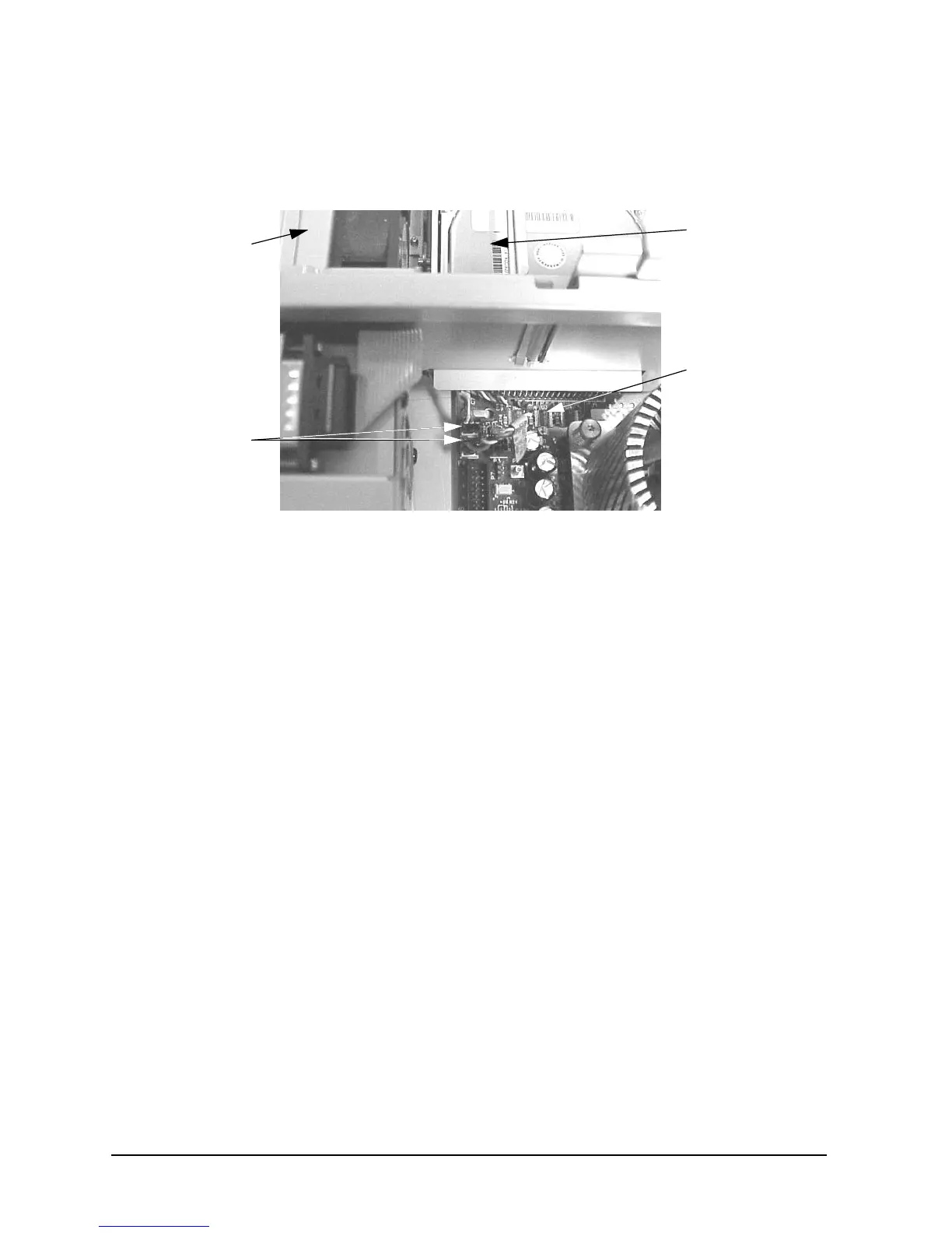
4. Plug in the two fan-module power cable’s connectors into their connectors on the system
board. See Figure 3-76.
Figure 3-76. Plugging in the Fan-Module Power Cables into the System Board
5. Complete the procedure in the section “Replacing the CD Drive” (steps 2 through
8; in this chapter), “Replacing the DAT Drive” (steps 2 through 7; in Appendix
F), or “Replacing the Flexible Disk Drive” (steps 2 through 9; in Appendix G).
6. Complete the procedure in the section “Replacing the Front Bezel and Top Cover”
found in this chapter.
7. Connect and turn on the power to your system.
8. Determine that your PCI area fan-module replacement was successful by checking the
workstation’s LCD for fan error messages. If LCD fan error messages appear, repeat
this procedure. If your LCD still displays fan error messages, contact your local HP
Support Representative.
Fan-Module
Power Cables
Fan Module
System Board
PCI Cage Area
 Loading...