Home
HP
Laptop
Compaq NX7300
Page 134
HP Compaq NX7300 - Page 134
242 pages
Manual
Save Page as PDF
To Next Page
To Next Page
To Previous Page
To Previous Page
Loading...
R
emo
val and R
eplacement Pr
ocedur
es
Maintenance and S
ervi
ce Guide
5–4
1
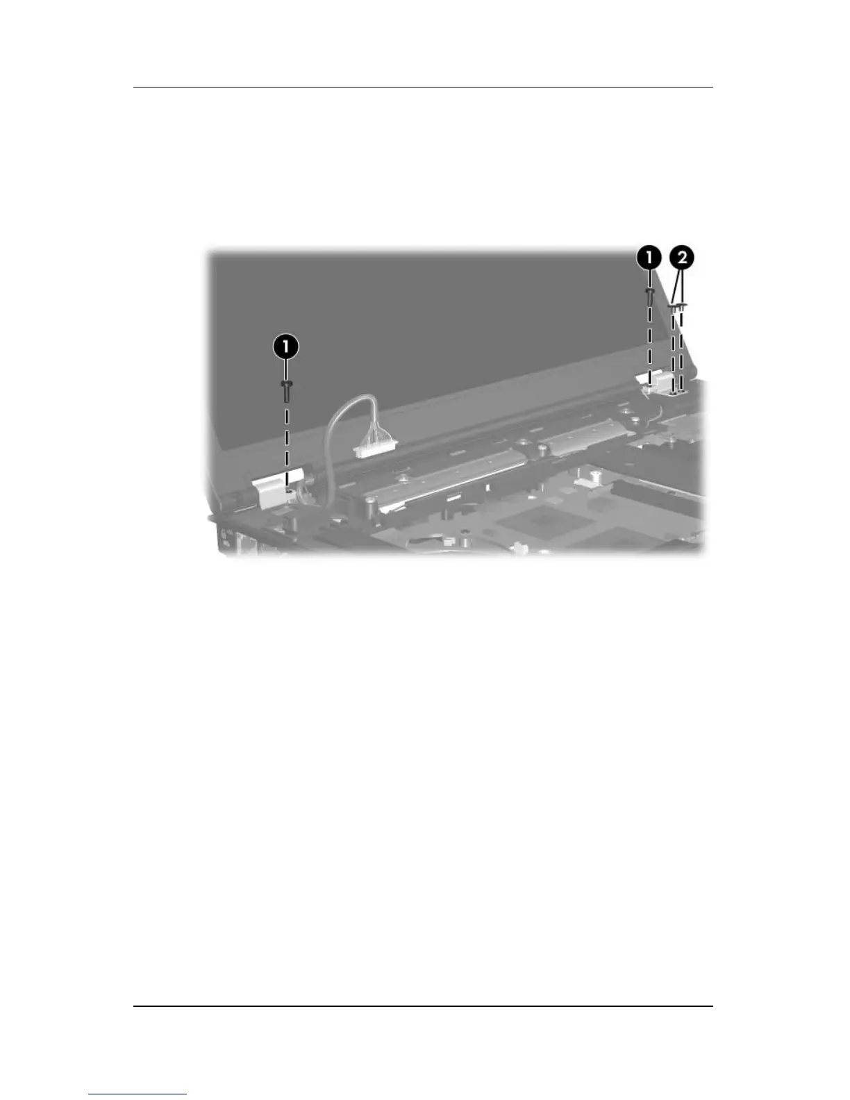
7.
Remov
e the two T
orx8 T8M2.5×10.0 scre
ws
1
and the
two
Phillips PM2.0×2.0 scre
ws
2
that secure the display
assembly to the
computer
.
R
emo
ving the Dis
play As
sembl
y Scr
e
ws
133
135
Table of Contents
Main Page
Default Chapter
4
Table of Contents
4
Specifications
7
1 Product Description
8
Features
9
Resetting the Computer
12
Power Management
13
External Components
14
Right-Side Components
16
Rear Panel Components
17
Left-Side Components
18
Top Components
23
Touchpad Components
25
Bottom Components
26
Design Overview
27
2 Troubleshooting
28
Starting Computer Setup
28
Navigating and Selecting in Computer Setup
29
Restoring Factory Settings in Computer Setup
30
File Menu
31
Security Menu
32
Diagnostics Menu
34
System Configuration Menu
34
Troubleshooting Flowcharts
37
Flowchart 2.1—Initial Troubleshooting
38
Flowchart 2.2—No Power, Part
39
Flowchart 2.3—No Power, Part
40
Flowchart 2.4—No Power, Part
41
Flowchart 2.5—No Power, Part
42
Flowchart 2.6—No Video, Part
43
Flowchart 2.7—No Video, Part
44
Flowchart 2.13—No os Loading, Diskette Drive
50
Flowchart 2.14—No os Loading, Optical Drive
51
Flowchart 2.15—No Audio, Part
52
Flowchart 2.16—No Audio, Part
53
Flowchart 2.17—Nonfunctioning Device
54
Flowchart 2.18—Nonfunctioning Keyboard
55
Flowchart 2.19—Nonfunctioning Pointing Device
56
3 Illustrated Parts Catalog
58
Serial Number Location
58
Computer Major Components
59
Plastics Kit
71
Mass Storage Devices
73
Miscellaneous (Not Illustrated)
75
Sequential Part Number Listing
78
4 Removal and Replacement Preliminaries
86
Tools Required
86
Service Considerations
87
Plastic Parts
87
Cables and Connectors
87
Preventing Damage to Removable Drives
88
Preventing Electrostatic Damage
89
Packaging and Transporting Precautions
90
Workstation Precautions
91
Grounding Equipment and Methods
92
Typical Electrostatic Voltage Levels
93
5 Removal and Replacement Procedures
94
Serial Number
95
Disassembly Sequence Chart
96
Preparing the Computer for Disassembly
98
Hard Drive
100
Computer Feet
104
Optical Drive
105
External Memory Module
107
Bluetooth Module
110
Keyboard
112
Thermal Plate
116
Fan Assembly
117
Heat Sink
118
Processor
121
Mini Card Module
123
Internal Memory Module
126
RTC Battery
128
Switch Cover
129
Display Assembly
132
Top Cover
136
Modem Module
140
System Board
142
System Board Frame (Full-Featured Models Only)
149
Usb/Audio Board
152
Hard Drives
158
System Dma
167
System Interrupts
168
System Memory Map
173
Screw Listing
174
Windows Vista
197
Backup Suggestions
198
Backing up Specific Files or Folders
199
Backing up the Entire Hard Drive
199
Creating Recovery Points
200
Scheduling Backups
201
Performing a Recovery
201
Performing a Recovery from the Hard Drive
202
Initiating a Recovery in Windows
202
Recovery Partition
203
Creating Recovery Discs
204
Backing up Your Information
205
Connector Pin Assignments
226
Universal Serial Bus
228
External Monitor
229
Power Cord Set Requirements
232
Conductor Power Cord Set
232
General Requirements
233
Other manuals for HP Compaq NX7300
Getting Started
57 pages
Quickspecs
35 pages
Supplementary Guide
21 pages
Related product manuals
HP Compaq NX7400
9 pages
HP Compaq NX7000
186 pages
HP Compaq NX9005
2 pages
HP Compaq nx6110
237 pages
HP Compaq nx6125
224 pages
HP Compaq NX9020
50 pages
HP Compaq NX6315
78 pages
HP Compaq nx6115
224 pages
HP Compaq nx6310
36 pages
HP Compaq NX9420
17 pages
HP Compaq NX6120
201 pages
HP Compaq NX6320
39 pages
 Loading...