5–52 Maintenance and Service Guide
Removal and Replacement Procedures
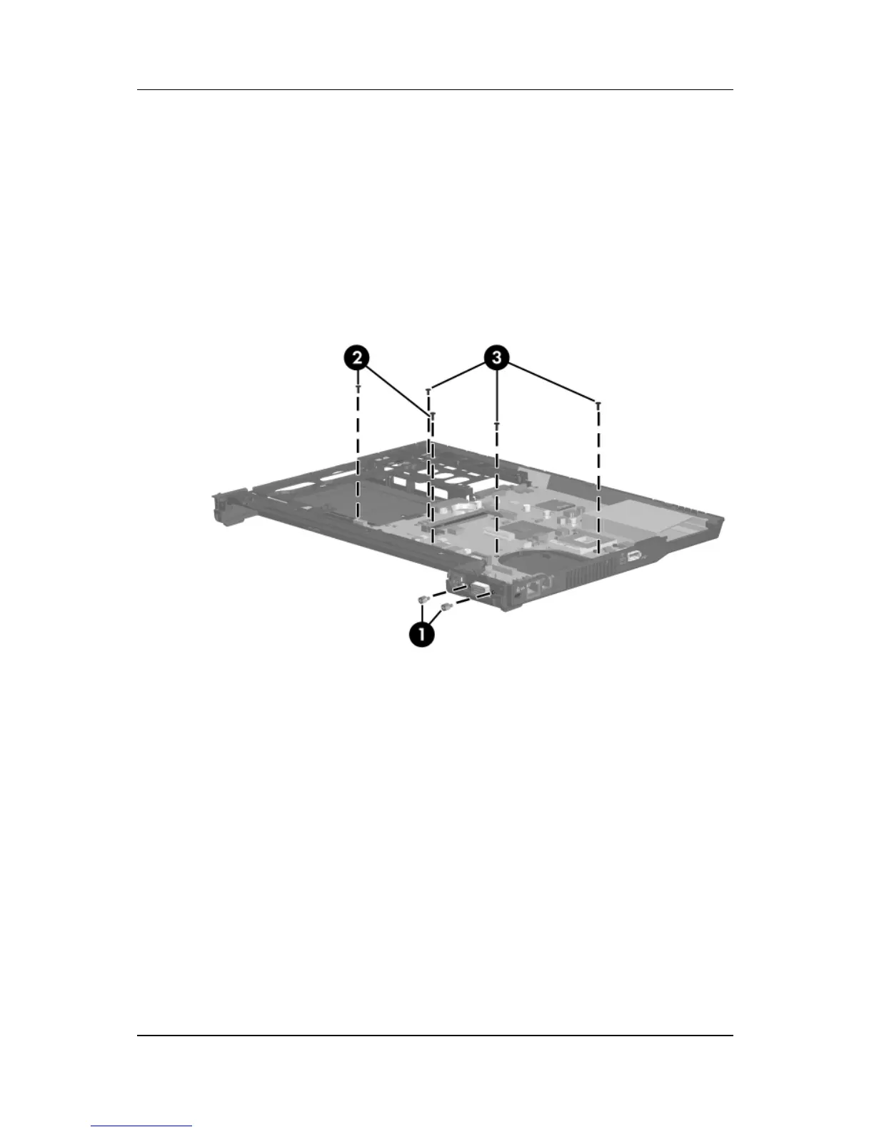
4. Remove the following:
1 Two HM5.0×10.0 screw locks on each side of the external
monitor connector
2 Two Torx T8M2.5×6.0 screws (full-featured model only)
3 Three Torx T8M2.5×4.0 screws (the defeatured model
uses four torx screws)
Removing the System Board Screws and Screw Locks (full-featured
model shown)
 Loading...