5–26 Maintenance and Service Guide
Removal and Replacement Procedures
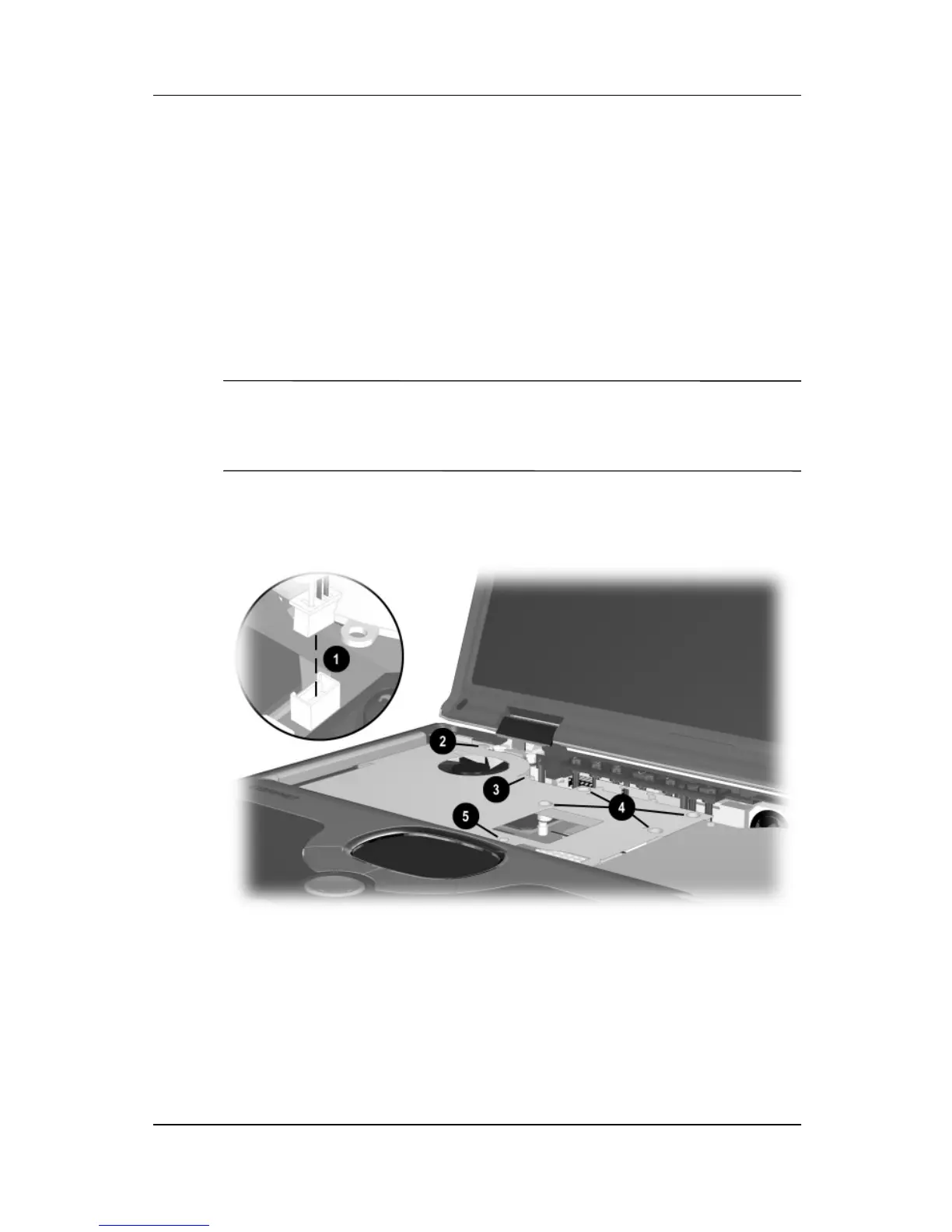
4. Disconnect the fan cable
1
from the system board
(Figure 5-20).
5. Remove the following screws:
❏
One TM2.5 × 5.0 screw
2
next to the fan
❏
One TM2.5 × 5.0 screw
3
that secures the display video
cable ground loop
❏
Four spring-loaded TM2.5 × 14.0 shoulder screws
4
✎
The four spring-loaded shoulder screws should be removed and
installed in the “1,” “2,” “3,” “4” sequence stamped on the heat
spreader adjacent to each screwhole.
❏
One TM2.5 × 8.0 screw
5
next to the keyboard and
TouchPad ZIF connectors
Figure 5-20. Removing the Heat Spreader Screws
 Loading...