7.
Disconnect the battery charger board ribbon cable from the system board (see
Battery connector
board on page 52).
8. Remove the top cover (see
Top cover on page 54).
9. Disconnect the optical drive cable from the system board (see
Optical drive on page 63).
10. Remove the system board (see
System board on page 66).
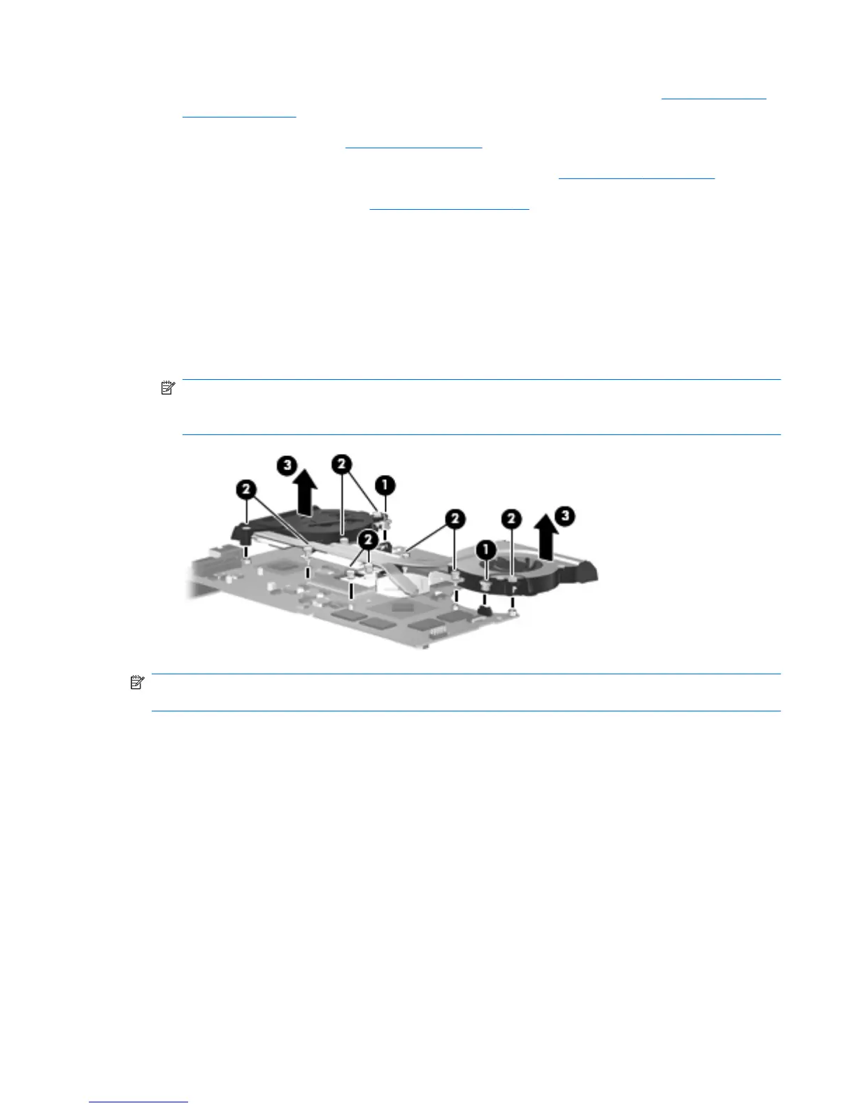
Remove the fan/heat sink assembly:
1.
Turn the system board upside down with the front toward you.
2. Disconnect the two fan cables (1) from the system board.
3. Loosen the nine captive screws (2) that secure the fan/heat sink assembly to the system board.
4. Remove the fan/heat sink assembly (3).
NOTE: Due to the adhesive quality of the thermal material located between the fan/heat sink
assembly and system board components, it may be necessary to move the fan/heat sink assembly
from side to side to detach it.
NOTE: The thermal material must be thoroughly cleaned from the surfaces of the fan/heat sink
assembly and the processor each time the fan/heat sink assembly is removed.
●
Thermal paste is used on the processor (1) and the heat sink section (2) that services it
●
A thermal pad is used on the PCH chip (3) and the heat sink section (4) that services it
●
Thermal paste is used on the graphics subsystem chip (5) and the heat sink section (6) that
services it
Replacement thermal material is included with all fan/heat sink assembly, system board, and processor
spare part kits.
ENWW
Component replacement procedures
71

 Loading...