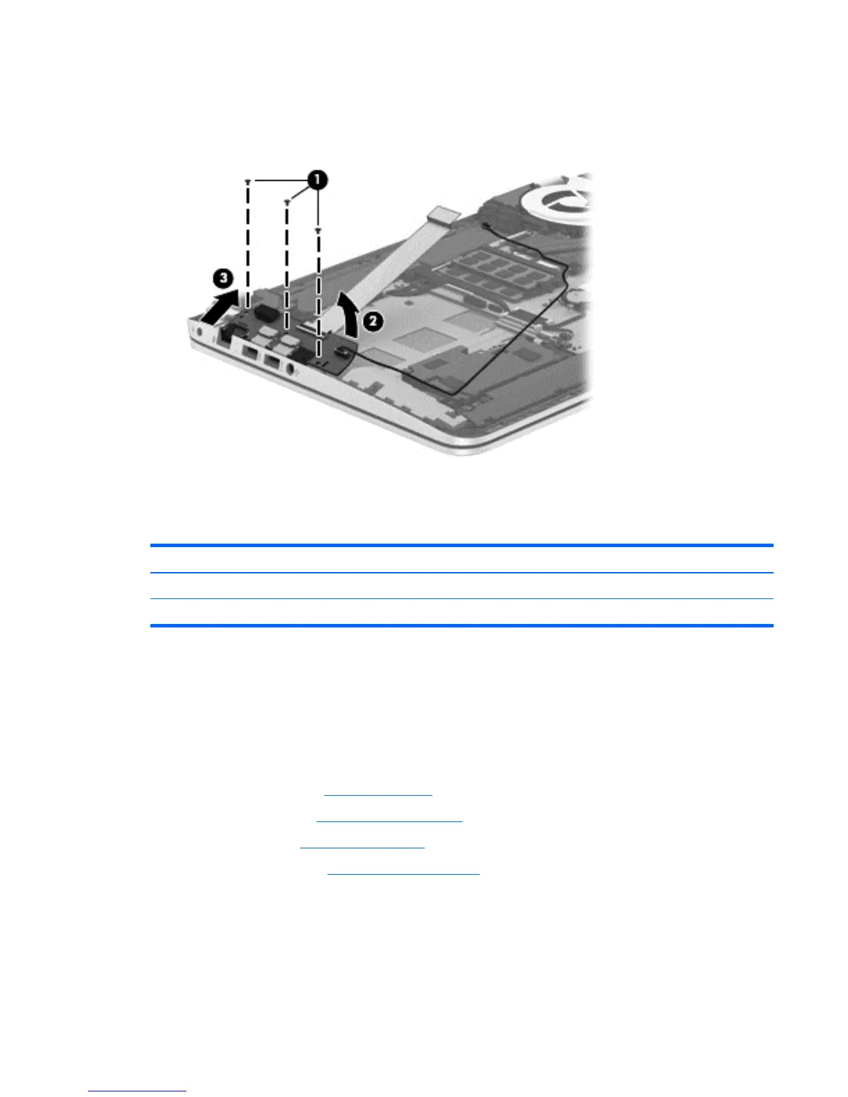
5. Remove the three Phillips PM2.0×2.9 screws (1) that secure the connector board to the top cover.
6. Lift the right side of the connector board (2) until it rests at an angle.
7. Remove the connector board (3) by sliding it up and to the right at an angle.
Reverse this procedure to install the connector board.
Power connector cable
Description Spare part number
Power connector cable for use in models with UMA graphics 720537-001
Power connector cable for use in models with discrete graphics 720538-001
Before removing the power connector cable, follow these steps:
1. Turn off the computer. If you are unsure whether the computer is off or in Hibernation, turn the
computer on, and then shut it down through the operating system.
2. Disconnect the power from the computer by unplugging the power cord from the computer.
3. Disconnect all external devices from the computer.
4. Remove the battery (see
Battery on page 34), and then remove the following components:
a. Service cover (see
WLAN module on page 35)
b. Hard drive (see
Hard drive on page 38)
c. Base enclosure (see
Base enclosure on page 45)
Remove the power connector cable:
1. Disconnect the power cable (1) from the system board.
2. Release the power connector cable from the clips (2) built into the keyboard shield.
Component replacement procedures 65
 Loading...