Connector board
NOTE: The connector board spare part kit includes the audio jack, RJ-45 jack, USB port, and 2 cables.
Description Spare part number
For use only on computer models equipped with a graphics subsystem with discrete memory 765146-001
For use only on computer models equipped with a graphics subsystem with UMA memory 765145-001
Before removing the connector board, follow these steps:
1. Turn off the computer. If you are unsure whether the computer is off or in Hibernation, turn the
computer on, and then shut it down through the operating system.
2. Disconnect the power from the computer by unplugging the power cord from the computer.
3. Disconnect all external devices from the computer.
4. Remove the battery (see
Battery on page 34), and then remove the following components:
a. Service cover (see
WLAN module on page 35)
b. Hard drive (see
Hard drive on page 38)
c. Base enclosure (see
Base enclosure on page 45)
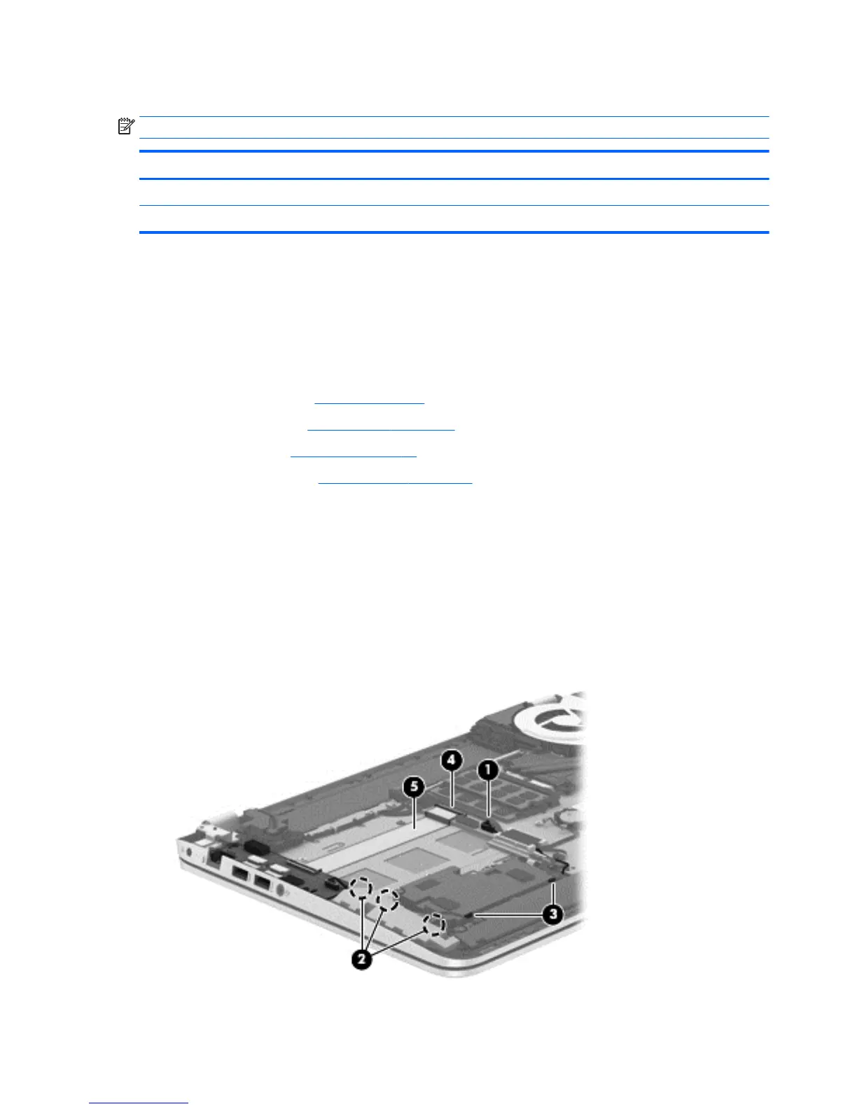
Remove the connector board:
1. Disconnect the connector board cable (1) from the system board.
2. Release the connector board cable from the retention clips built into the top cover (2) and the
subwoofer (3).
3. Release the ZIF connector (4) to which the connector board ribbon cable is attached, and then
disconnect the connector board ribbon cable from the system board.
4. Detach the connector board ribbon cable (5) from the base enclosure. (The connector board ribbon
cable is attached to the top cover with double-sided tape.)
64 Chapter 6 Removal and replacement procedures for Authorized Service Provider parts
 Loading...