a. Service cover (see WLAN module on page 35)
b. Hard drive (see
Hard drive on page 38)
c. Base enclosure (see
Base enclosure on page 45)
d. Display assembly (see
Display assembly on page 47)
e. Fan (see
Fan on page 55)
f. System board (see
System board on page 56)
g. Heat sink (see
Heat sink on page 60)
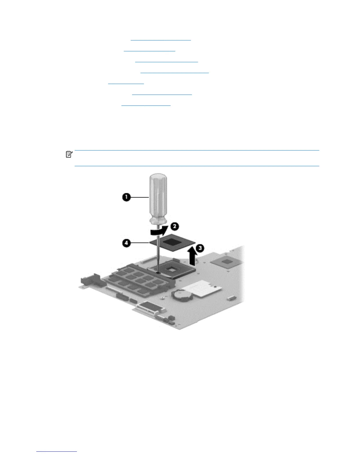
Remove the processor:
1. Use a flat-bladed screw driver (1) to turn the processor locking screw one-half turn counterclockwise
(2), until you hear a click.
2. Lift the processor (3) straight up, and remove it.
NOTE: The gold triangle (4) on the processor must be aligned with the triangle icon embossed on the
processor socket when you install the processor.
Reverse this procedure to install the processor.
Component replacement procedures 63
 Loading...