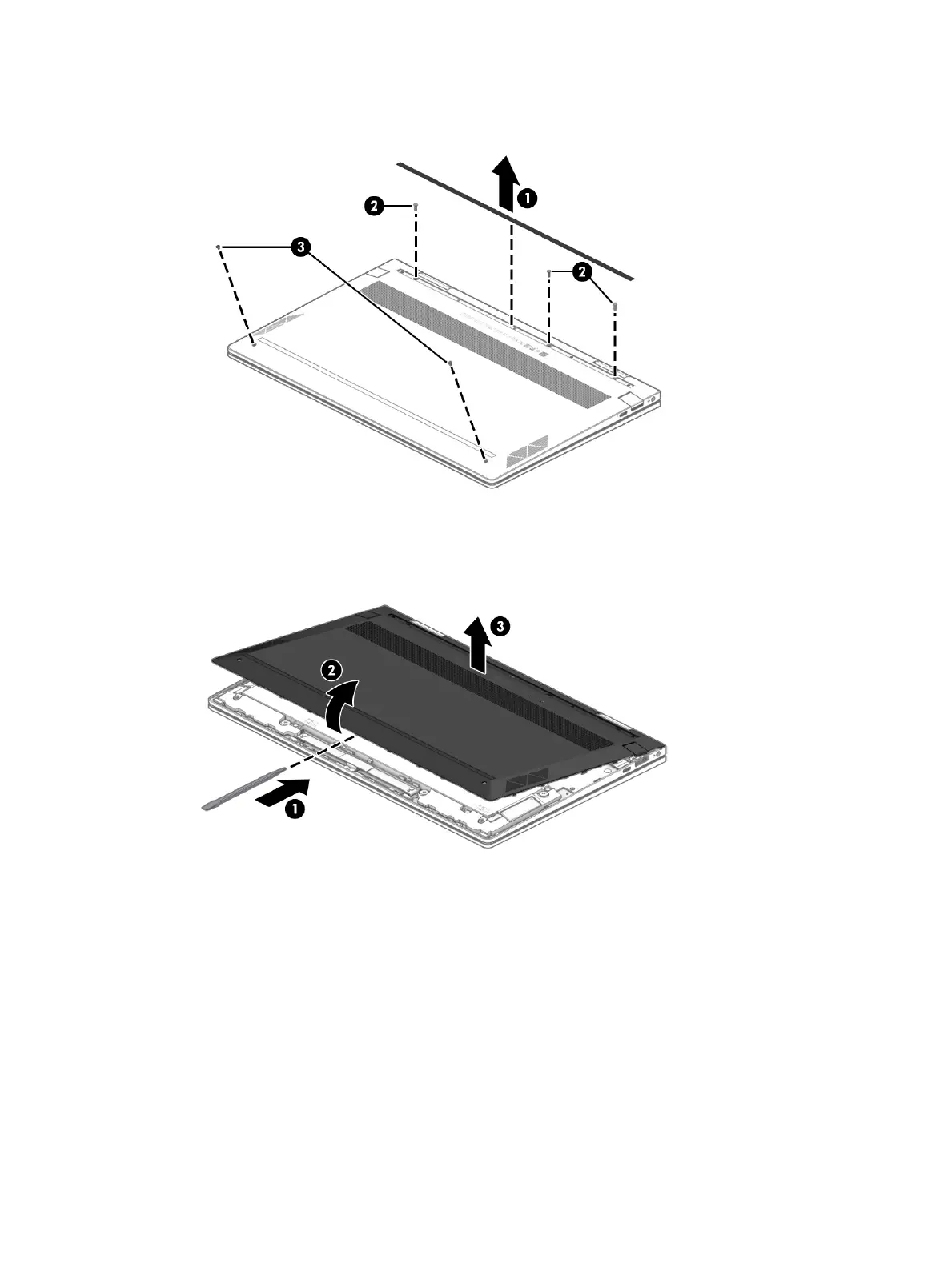
6. Remove the three Phillips M2.5×5.3 screws (2) and the two Torx5 M2.0×2.7 screws (3) that secure
the bottom cover to the keyboard/top cover.
7. Use a case utility tool or similar thin plastic tool (1) to separate the front edge of the bottom cover (2) from
the keyboard/top cover.
8. Remove the bottom cover (3).
Each time the bottom cover is removed and replaced, inspect the adhesive tape located on the AC adapter and
battery light pipe (1) and the audio-out (headphone)/audio-in (microphone) combo jack (2). This tape ensures
that the bottom cover ts snugly at these contact points. Replacement adhesive tape should be 0.3 mm in
thickness.
The bottom cover adhesive tape is available using spare part number M11730-001.
Component replacement procedures 31

 Loading...