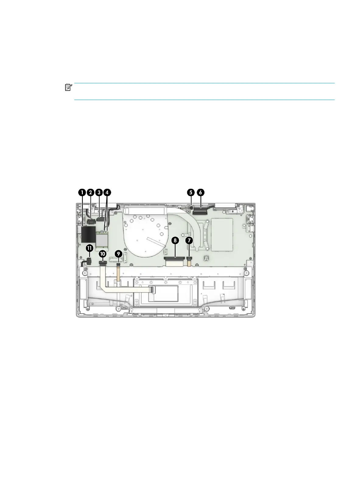
2. Disconnect the following cables from the system board:
(2) Power connector cable
(3) Webcam/microphone module ZIF connector cable
(4) WLAN antenna cables
NOTE: The #1/white WLAN antenna cable connects to the WLAN module #1/Main terminal. The #2/black
WLAN antenna cable connects to the WLAN module #2/Aux terminal.
(5) Infrared board ZIF connector cable
(6) Display panel ZIF connector cable
(7) Backlight ZIF connector cable
(8) Keyboard ZIF connector cable
(9) Fingerprint reader ZIF connector cable
(10) Touchpad ZIF connector cable
(11) Speaker cable
3. Remove the three Phillips M2.0×2.3 broad head screws (1) that secure the system board to
the keyboard/top cover.
Component replacement procedures 59

 Loading...