Spanning Tree Protocol 58
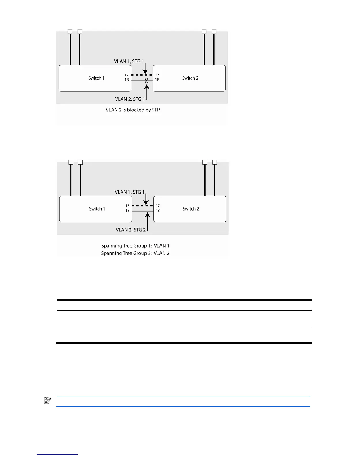
Figure 9 Two VLANs on one instance of Spanning Tree Protocol
In the following figure, VLAN 1 and VLAN 2 belong to different Spanning Tree Groups. The two instances of
spanning tree separate the topology without forming a loop, so that both VLANs can forward packets between the
switches without losing connectivity.
Figure 10 Two VLANs on separate instances of Spanning Tree Protocol
VLAN participation in Spanning Tree Groups
The following table shows which switch ports participate in each Spanning Tree Group. By default, server ports (ports
1-16) do not participate in Spanning Tree, even though they are members of their respective VLANs.
Table 12 VLAN participation in Spanning Tree Groups
VLAN 1 VLAN 2
Switch 1 Spanning Tree Group 1
Port 17
Spanning Tree Group 2
Port 18
Switch 2 Spanning Tree Group 1
Port 17
Spanning Tree Group 2
Port 18
Configuring Multiple Spanning Tree Groups
This section explains how to assign each VLAN to its own Spanning Tree Group on the switches 1 and 2.
By default, Spanning Tree Groups 2-127 are empty, and Spanning Tree Group 1 contains all configured VLANs until
individual VLANs are explicitly assigned to other Spanning Tree Groups. Except for the default Spanning Tree Group
1, which may contain more than one VLAN, Spanning Tree Groups 2-128 may contain only one VLAN each.
NOTE: Each instance of Spanning Tree Group is enabled by default.

 Loading...