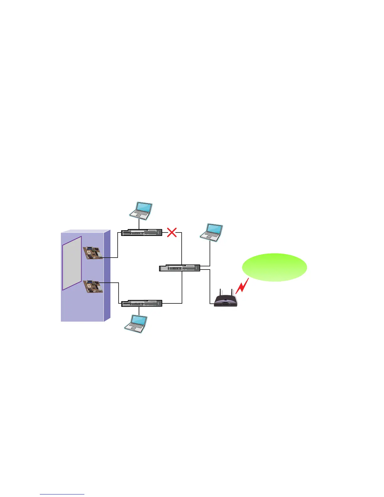
unplugged/disconnected. This results in the HP Integrity server being effectively disconnected
from the entire network except for Switch A. Only the 50 users on Switch A can access the server,
whereas the 50 users on Switch B, the 250 users connected via the Core Switch, and the router
connection to any external network can no longer communicate with the server. Even though a
non-Primary port is connected to this isolated segment, non-Primary ports in an NFT team are
not used for any transmit or receive communication. If this was a TLB team instead of an NFT
team the server would still only be able to communicate with the network represented by Switch
A since only Primary ports can receive traffic from the network.
When this type of situation occurs on the network, it would be better for the server to proactively
failover and choose a new primary from one of the team ports that still has connectivity with
the core segment. In addition, the team should discontinue the use of any teamed ports that don’t
have connectivity with the core segment to prevent transmitting on a teamed port that can’t
reach the intended target (for example, client, router, etc.).
The use of heartbeat frames between teamed ports will not provide enough information for the
teaming driver to make the best failover decision. In other words, if the Primary port can’t receive
heartbeat frames from the non-Primary and vice versa, the only thing the teaming driver knows
is that the teamed ports are no longer attached to the same network segment. The teaming driver
still doesn’t know which network segment is the best segment to choose.
Figure 4-4 Upstream link failures cause server isolation
To solve this problem, HP Engineering developed the Active Path mechanism. The Active Path
mechanism allows the teaming driver to actively monitor network connectivity on a per-team
member port basis with an external network device (designated as the Echo Node). Team member
ports that have connectivity with the Echo Node are considered to be “eligible for use by the
team”. Therefore, Active Path becomes another validation mechanism in addition to link loss,
transmit path validation, and receive path validation.
General Description of Active Path Operation
The goal of Active Path is to verify that each individual member port in a team has connectivity
to the designated Echo Node that is located on the “important” physical segment of the broadcast
domain. The method that Active Path uses must be able to operate independently of team member
roles (Primary, non-Primary). In other words, Active Path must be able to transmit Echo Node
probes and receive responses on each individual member port. Additionally, Active Path must
accomplish this without using the team’s IP address. The team’s IP address cannot be used since
38 The Mechanics of Teaming for the Advanced User
 Loading...