NOTE: This step may not occur if Blue’s ARP table still contains an entry for Red as a result
of Steps 1 and 2.
Blue checks its ARP cache for a MAC address entry that corresponds to 1.1.1.1. If Blue does
not find one (in other words, ARP cache timed out since last communication with Red), then
Blue broadcasts an ARP request asking for Red’s MAC address.
5. Red transmits a unicast ARP reply to Blue providing its MAC address (A).
NOTE: The following step will not occur if Step 4 does not take place.
Red sees the ARP request and transmits a unicast ARP reply directly to Blue providing its
MAC address (A). Blue receives the ARP reply and puts Red’s MAC address (A) and IP
address (1.1.1.1) in its ARP cache.
6. Blue transmits a unicast ping reply to Red using Red’s destination MAC address (A).
Blue transmits a unicast ping reply to Red using Red’s MAC address (A) and the user sees
the ping REPLY message printed on the screen. This completes the entire conversation.
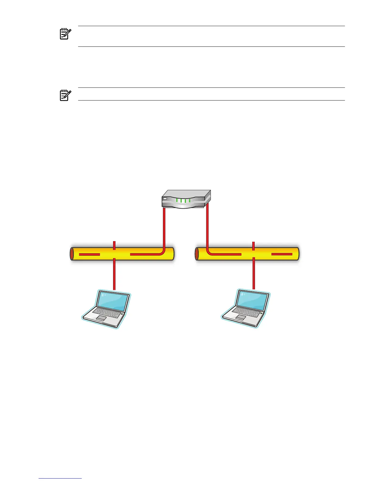
Scenario A-2: One Device Pings Another on a Different Layer 2 Network
Figure A-2 Scenario A-2: one device pings another on a different Layer 2 network
1. Red transmits a broadcast ARP request on Network 1.0.0.0 asking for Green’s MAC
address.
A user on Red issues the command ping 2.2.2.1 to initiate a ping to Blue. The number 2.2.2.1
refers to Blue’s IP address, or protocol address. First, Red determines whether or not Blue
is on the same Layer 2 network by running an algorithm (details of this algorithm are beyond
the scope of this document) using its own IP address of 1.1.1.1, its own subnet mask (not
shown), and Blue’s IP address of 2.2.2.1. If Blue is on a different Layer 2 network, then Red
will need to use its gateway or router (Green) to get to Blue.
Once Red has determined that Blue is on a different Layer 2 network, Red must use Green
as a gateway to get to Blue. Red communicates directly with Green at Layer 2 but
communicates directly with Blue at Layer 3. This means that Red must transmit a frame
with the Layer 2 address (MAC) of Green, but the same frame will have Blue’s Layer 3
address (IP) in it. When Green receives the frame, it sees the Layer 3 data destined for Blue
and forwards the frame onto Blue via Green’s interface that is attached to Blue’s Layer 2
network (Network 2.0.0.0). This means that Red must find out what Green’s MAC address
Example Scenarios of Network Addressing and Communication 91
 Loading...