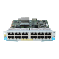
The following table shows the label and description for 5400R zl2 switch with LED status as ON:
DescriptionLabel
Fault LED1
Module Link and Mode LEDs2
Module Status LEDs3
When the module is installed properly and the switch is powered on, or the module is installed
when the switch already has power, the module undergoes a self test that takes a few seconds.
You can use the LEDs to determine that the module is installed properly and has passed the self
test, as described in the “LED Behavior” table below.
Table 1 LED Behavior
Display for a Properly Installed ModuleLED
(for the slot in which you are installing the module) The LED goes ON as soon as
the module is installed and the switch is powered on, and stays ON steadily.
Module Status
ON briefly while the module is being tested, then OFF.Test
NOTE: If the switch was powered off while the module was installed, when the
switch is powered on, the Test LED will stay ON for the duration of the whole switch
self test.
OFFFault
For a module that is installed when the switch is already powered on (hot swap), all
the Link and Mode LEDs on the module go ON for approximately 3 to 10 seconds,
Link and Mode (on the
modules)
then OFF for 5 to 10 seconds depending on the module. Then, the Test LED on the
switch goes OFF.
If the module is already installed when the switch is powered on or reset, the process
described above occurs approximately 30 seconds after the power on or reset, during
which the switch is being tested.
Error Condition
If the Link LED on the module is flashing orange and the Fault LED on the switch is on, then
there is a fault condition on the port with the flashing orange LED. The module letter, on the
Management Module corresponding to the module with the flashing orange LED will also be
flashing simultaneously.
Connecting the Network Cables
Connect the appropriate network cables to the module's ports as shown in the table below. For
more information on the cable specifications, see “Cabling and Technology Specifications” in
Cabling and Technology Specifications.
Module
10/100/1000–T PoE zl Module
16 Installing the Modules