Front panel components 11
MSA 1050 Array LFF or supported 12-drive expansion enclosure
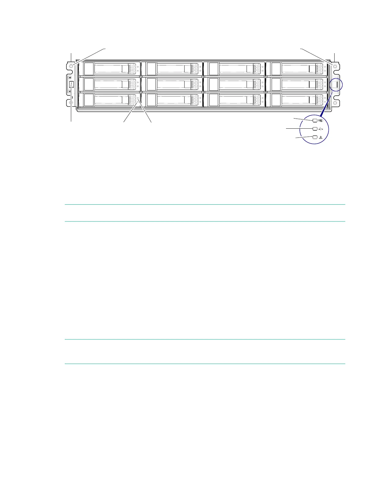
Figure 3 MSA 1050 Array LFF or supported 12-drive expansion enclosure: front panel
NOTE: Either the bezel or the ear covers should be attached to the enclosure front panel to protect ear circuitry.
You can attach either the enclosure bezel or traditional ear covers to the enclosure front panel to protect the ears, and
provide label identification for the chassis LEDs. The bezel and the ear covers use the same attachment mechanism,
consisting of mounting sleeves on the cover back face:
• The enclosure bezel is introduced in Figure 1 (page 10).
• The ear covers are introduced in Figure 22 (page 58).
• The ball studs to which the bezel or ear covers attach are labeled in Figure 2 (page 10) and Figure 3 (page 11).
• Enclosure bezel alignment for attachment to the enclosure front panel is shown in Figure 21 (page 58).
• The sleeves that push-fit onto the ball studs to secure the bezel or ear covers are shown in Figure 22 (page 58).
Disk drives used in MSA 1050 enclosures
MSA 1050 enclosures support LFF/SFF Midline SAS and LFF/SFF Enterprise SAS disks, and LFF/SFF SSDs. For information
about creating disk groups and adding spares using these different disk drive types, see the SMU Reference Guide.
NOTE: In addition to the front views of SFF and LFF disk modules shown in the figures above, see Figure 26 (page 61)
for pictorial views.
1 Enclosure ID LED
2 Disk drive Online/Activity LED
3 Disk drive Fault/UID LED
4 Unit Identification (UID) LED
5 Heartbeat LED
6 Fault ID LED
132
4
5
6
1
2
3
4
5
6
7
8
9
10
11
12
Left ear
Right ear
Notes:
Integers on disks indicate drive slot numbering sequence.
The enlarged detail view at right shows LED icons from the bezel that correspond to the chassis LEDs.
Bezel icons for LEDs
Ball stud (two per ear flange) Ball stud (two per ear flange)
The detail view locator circle (above right) identifies the ear kit that connects to LED light pipes in the bezel (or ear cover).