LED behavior
During the self test:
• Initially, all the controller and port LEDs are on. Most of the LEDs turn off and then may turn
on again during phases of the self test.
• For the duration of the self test, the Test LED stays on.
When the self test completes successfully:
• The Power LED remains on.
• The Fault, Locator and Test LEDs stay off.
• The Act LED remains on indicating the default port LED mode.
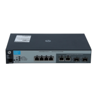
• The port LEDs on the front of the controller go into their normal operational mode:
If the ports are connected to active network devices, the Link LEDs stay on and the Mode
LEDs behave according to the mode selected. In the default mode (Act), the Mode LEDs
blink to indicate port activity.
◦
◦ If the ports are not connected to active network devices, the Link and Mode LEDs will stay
off.
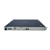
Mount the controller
After the controller passes self test, it is ready to be mounted in a stable location. The controller
can be mounted in these ways:
• In a rack or cabinet
• On a horizontal surface
• On a wall
Rack or cabinet mounting
The controller is designed to be mounted in any EIA-standard 19-inch telco rack or communication
equipment cabinet. The controller can also be mounted in a cabinet with the provided brackets.
Note that the mounting brackets have multiple mounting holes and can be rotated allowing for a
wide variety of mounting options. Secure the rack in accordance with the manufacturer's safety
guidelines.
NOTE: The 12-24 screws supplied with the controller are the correct threading for standard
EIA/TIA open 19-inch racks. If installing the controller in an equipment cabinet such as a server
cabinet, use the clips and screws that came with the cabinet in place of the 12-24 screws that are
supplied with the controller.
NOTE: Optional accessories have to be mounted at the same time as the mounting brackets.
See “Installing optional accessories” (page 15).
10 Installing the controller
 Loading...