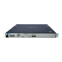
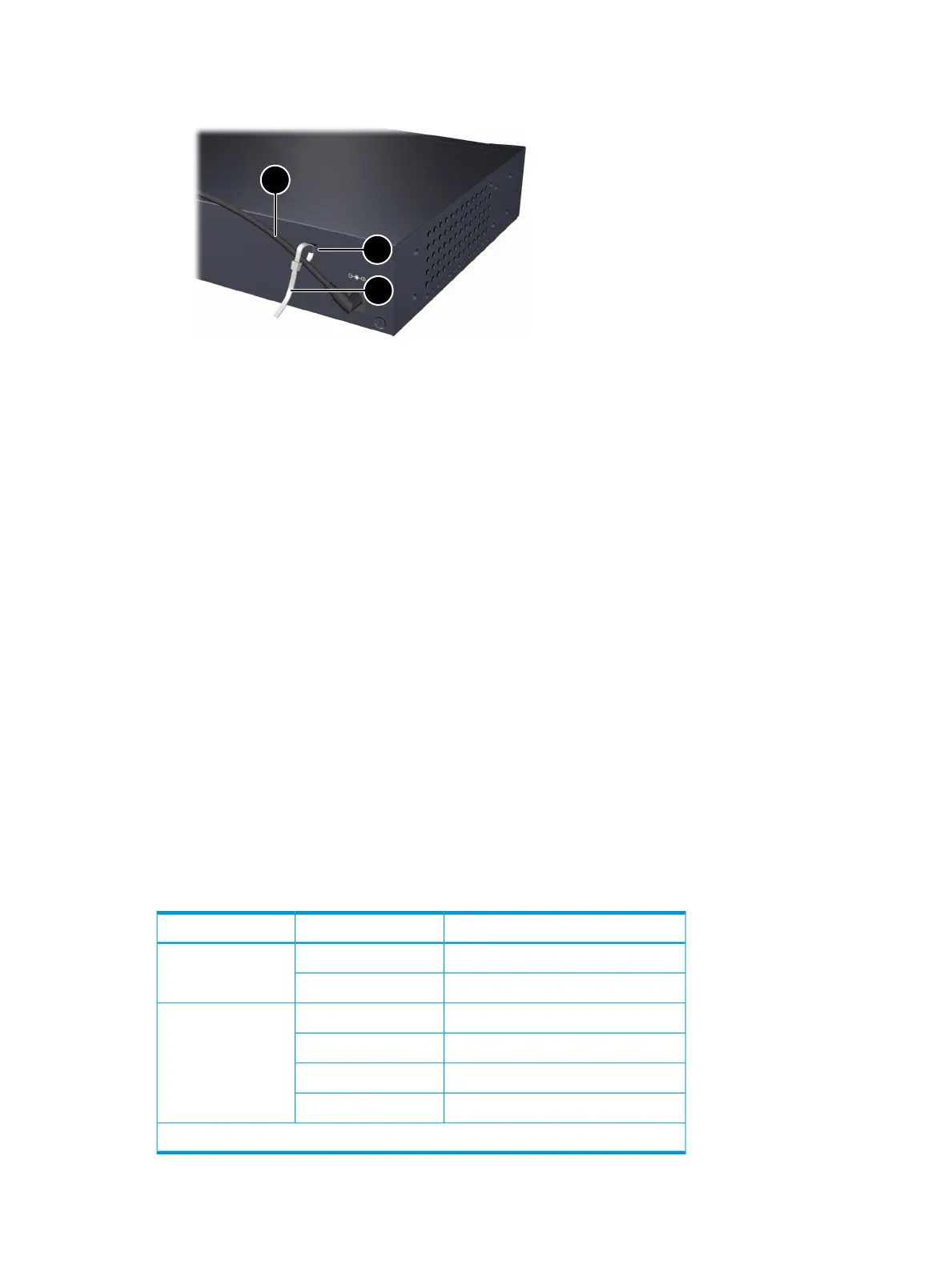
3. Secure the power cord to the controller with the provided cable tie.
Figure 9 Securing the power cord to the controller
3. Cable tie anchor2. Cable tie1. Power cable
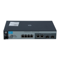
Connect the network cables
Connect the network cables from the network devices or patch panels to the controller.
Using the RJ-45 connectors
To connect:
Push the RJ-45 plug into the RJ-45 port until the tab on the plug clicks into place. The Link LED lights
when the devices at either end of the cables are powered on.
To disconnect:
Press the small tab on the plug and pull the plug out of the port.
Installing or removing optional mini-GBICs
You can install or remove an optional mini-GBIC from a mini-GBIC slot without having to power
off the controller. Use only HP mini-GBICs.
Mini-GBIC information
Dual-personality ports use either the 10/100/1000Base-T RJ-45 connector, or a supported HP
mini-GBIC (Small Form Factor Pluggable (SFP)) for fiber-optic connection. By default, the RJ-45
connectors are enabled.
The optional mini-GBICs add support for these speeds and technologies:
Table 4 Optional network speeds and technologies
Cabling*TechnologySpeed
Fiber (multimode)100-FX100 Mbps
Fiber (single mode)100-BX
Fiber (multimode)1000-SX1 Gbps
Fiber (multimode or single mode)1000-LX
Fiber (single mode)1000-LH
Fiber (single mode)1000-BX
*See also “Cabling and safety standards” (page 25).
Installation procedures 13
 Loading...