Removal and Replacement Procedures
Maintenance and Service Guide 5–45
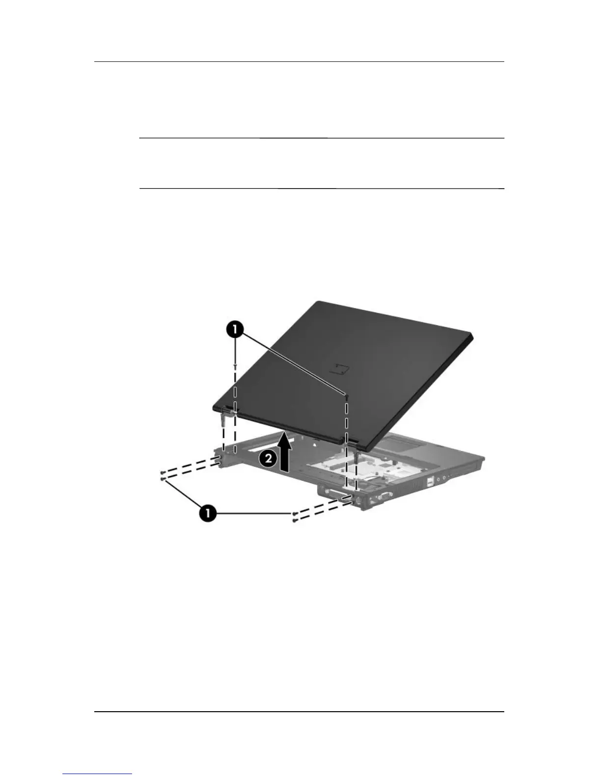
7. Swing the display assembly into a partially closed position.
8. Position the computer with the rear panel toward you.
Ä
CAUTION: Support the display assembly when removing the following
screws. Failure to support the display assembly can result in damage to
the display assembly and other computer components.
9. Remove the six Torx8 T8M2.5×9.0 screws 1 that secure the
display assembly to the computer.
10. Lift the display assembly 2 straight up and remove it.
Removing the Display Assembly
Reverse the above procedure to reassemble and install the
display assembly
 Loading...