Removal and Replacement Procedures
Maintenance and Service Guide 5–63
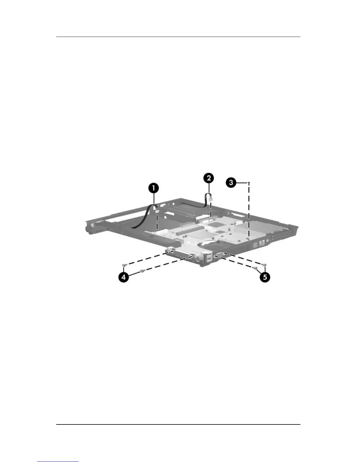
2. Disconnect the serial connector cable 1 and the Bluetooth
cable 2 from the system board.
3. Remove the Torx8 T8M2.5×4.0 screw 3 that secures the
system board to the base enclosure next to the RJ-11
connector.
4. Remove the two HM5.0×9.0 screw locks 4 on each side of
the parallel connector.
5. Remove the two HM5.0×9.0 screw locks 5 on each side
of the external monitor connectors.
Removing the System Board Screws and Screw Locks
 Loading...