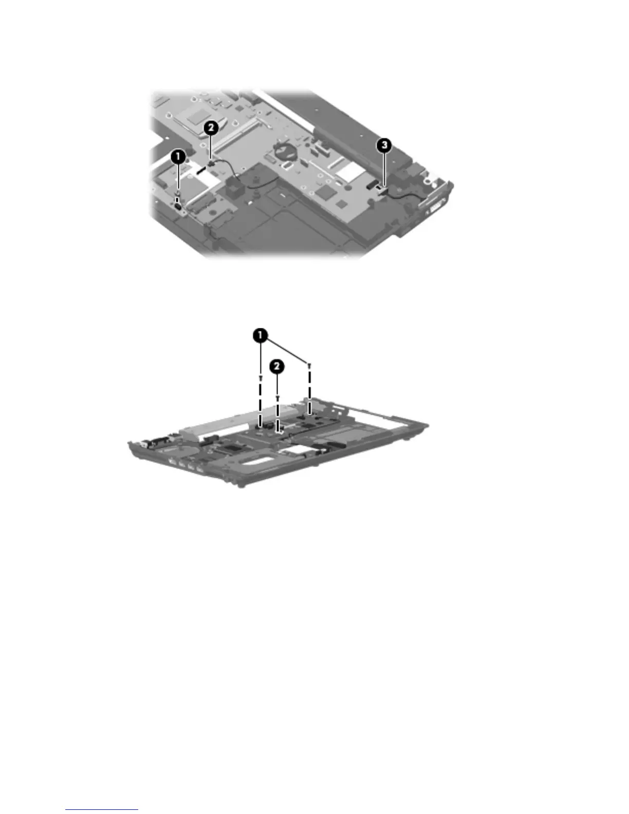
●
External monitor cable (3) from the system board
2. Remove the three slotted Torx T8M2.5×7.0 screws (1) and (2) that secure the system board to the
base enclosure. The front-most screw 2 is present only on computer models equipped with a 15.6-
in display assembly.
3. Use the middle of the system board (1) to lift the right side (2) of the system board until it rests at
an angle.
138 Chapter 4 Removal and replacement procedures

 Loading...