dual-headed cable with the first connector routed to the 3.5-inch hard drive bay and the second
connector routed to the 2.5-inch hard drive bay.
●
You must install guide screws to ensure the drive will line up correctly in the drive cage and lock in
place. HP has provided four extra 6-32 standard guide screws installed on the top of the drive bay. The
6-32 standard guide screws are required for a media card reader or a secondary hard drive installed in
the 3.5-inch optional drive bay. M3 isolation mounting guide screws for 2.5-inch hard drives are not
provided. If you are replacing a drive, remove the guide screws from the old drive and install them in the
new drive.
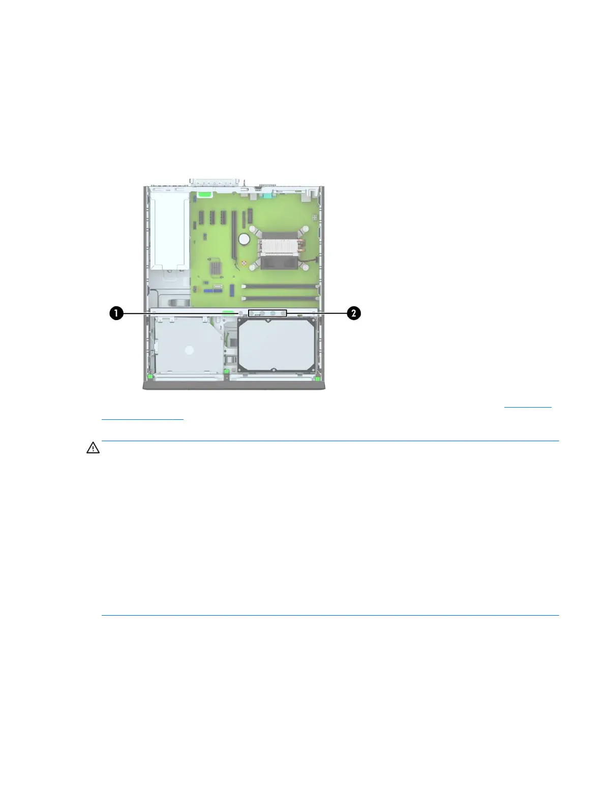
There are a total of five extra silver 6-32 standard screws. One is used for bezel security (1) (see Front bezel
security on page 22 for more information). The other four are used as guide screws for a media card reader or
a secondary hard drive in the 3.5-inch optional drive bay (2).
CAUTION: To prevent loss of work and damage to the computer or drive:
If you are inserting or removing a drive, shut down the operating system properly, turn off the computer, and
unplug the power cord. Do not remove a drive while the computer is on or in standby mode.
Before handling a drive, ensure that you are discharged of static electricity. While handling a drive, avoid
touching the connector.
Handle a drive carefully; do not drop it.
Do not use excessive force when inserting a drive.
Avoid exposing a hard drive to liquids, temperature extremes, or products that have magnetic fields such as
monitors or speakers.
If a drive must be mailed, place the drive in a bubble-pack mailer or other protective packaging and label the
package “Fragile: Handle With Care.”
Drives 33
 Loading...