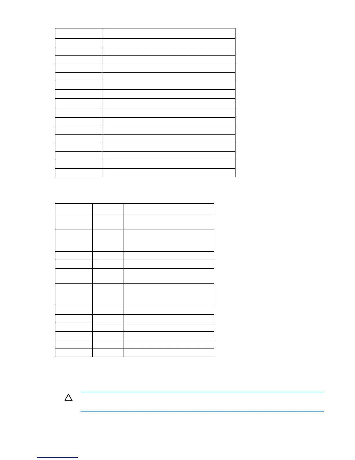
Component identification 12
Item Description
13
Internal USB tape connector
14
Discovery service cable connector
15
System battery
16
SATA connectors
17
Internal USB connector
18
Processor 2 DIMM slots
19
TPM connector
20
System maintenance switch
21
NMI header
22
Slot 9 PCIe3 x8 (4, 1)
23
Slot 8 PCIe3 x16 ( 16, 8, 4, 1)
24
Slot 7 PCIe3 x8 (4, 1)
25
Slot 6 PCIe3 x16 (16, 8, 4, 1)
26
Slot 5 PCIe2 x8 (4, 1)
27
Processor 1 DIMM slots
28
Processor socket 1 (populated)
System maintenance switch
Position Default Function
S1
Off Off = iLO 4 security is enabled.
On = iLO 4 security is disabled.
S2
Off Off = System configuration can be
changed.
On = System configuration is locked.
S3
Off Reserved
S4
Off Reserved
S5
Off Off = Power-on password is enabled.
On = Power-on password is disabled.
S6
Off Off = No function
On = ROM reads system configuration
as invalid.
S7
— Reserved
S8
— Reserved
S9
— Reserved
S10
S11
— Reserved
S12
— Reserved
To access the redundant ROM, set S1, S5, and S6 to on.
When the system maintenance switch position 6 is set to the On position, the system is prepared to erase all
system configuration settings from both CMOS and NVRAM.
CAUTION: Clearing CMOS and/or NVRAM deletes configuration information. Be sure to
properly configure the server or data loss could occur.
 Loading...