Do you have a question about the HP V1910 Series and is the answer not in the manual?
This documentation set is intended for network planners, field technical support and servicing engineers, and network administrators.
This section describes the conventions used in this documentation, covering GUI conventions and symbols.
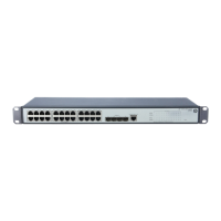
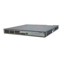
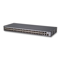
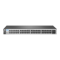
Describes the HP V1910 Switch Series as a line of Layer 2 Gigabit Ethernet switching products designed for high performance and ease of use.
This section provides essential safety recommendations to prevent device impairment and bodily injury during installation.
Details the requirements for examining the installation site, ensuring adequate clearance, ventilation, and stability for the switch.
Specifies the recommended temperature and humidity levels for proper operation and longevity of the switch.
Explains electromagnetic interference and provides actions to prevent EMI for the switch.
Highlights that the V1910 Switch Series is a class 1 laser device and warns about staring into optical ports.
Details the specifications and connection service for the console port on the front panel of each V1910 switch.
Describes the 10/100/1000Base-T Ethernet ports on the front panel, including their specifications and quantity.
Explains the 1000Base-X SFP interfaces on the front panel and the supported transceiver modules.
Explains the function of the power LED and describes its status indicators for switch operation.
Details the RPS status LED on the HP V1910-24G-PoE (365W) Switch JE007A and its status indications.
Provides information on the mounting brackets for the V1910 Switch Series and their appearance, mounting position, and description.
Details the steps and precautions for attaching the mounting brackets to the switch chassis, noting variations by switch model.
Provides step-by-step instructions for connecting the switch grounding cable to a grounding strip using an OT terminal.
Provides steps for connecting the AC power cord to the switch and the power source, ensuring proper grounding before powering on.
Explains how to set up the configuration environment by connecting a terminal (PC) to the console port with a console cable.
Describes the console cable, its connectors, and provides pinout information for RJ-45 and DB-9.
Lists essential checks to perform before powering on the switch, ensuring correct power cord and console connections.
Describes the Boot ROM display style and the process of powering on the switch, using an example model.
Provides a procedure to identify and resolve software loading failures, including common input errors and contact points.
Explains how to recover from console login password loss by using the Boot ROM menu and addresses Boot ROM password loss.
Details how to identify AC input failures by checking system status LEDs and related components.
Explains how to identify RPS input failures by checking system status or RPS status LEDs and connected components.
Describes how to identify failures when using concurrent AC and RPS power inputs by checking power and RPS status LEDs.
Troubleshoots issues where the configuration terminal displays nothing, checking power supply and console cable connections.
Provides steps to troubleshoot garbled terminal display by checking terminal settings like baud rate, data bits, parity, stop bits, and emulation.
| Model | HP V1910 Series |
|---|---|
| Ports | 8, 24, or 48 |
| Uplink Ports | Varies by model |
| Switching Capacity | Varies by model (Up to 104 Gbps) |
| Forwarding Rate | Varies by model (Up to 77.3 Mpps) |
| Layer | Layer 2 |
| Management | Web-managed |
| VLAN Support | Yes |
| QoS | Yes |
| MAC Address Table Size | 8, 192 entries |
| Jumbo Frame Support | Yes |
| Power Supply | Internal |
| Power Consumption | Varies by model |
| Dimensions | Varies by model |
| Weight | Varies by model |
| Operating Temperature | 32°F to 113°F (0°C to 45°C) |
| Operating Humidity | 10% to 90% (non-condensing) |