21
CAUTION:
Correctly connecting the switch grounding cable is crucial to the lightning protection and EMI protection.
The power interface and grounding terminals in this section are for illustration only.
The power input end of the switch has a noise filter, whose central ground is directly connected to the
chassis to form the chassis ground. You must securely connect this chassis ground to the earth so that the
faradism and leakage electricity can be safely released to the earth to minimize EMI susceptibility of the
switch.
Grounding the switch with a grounding strip
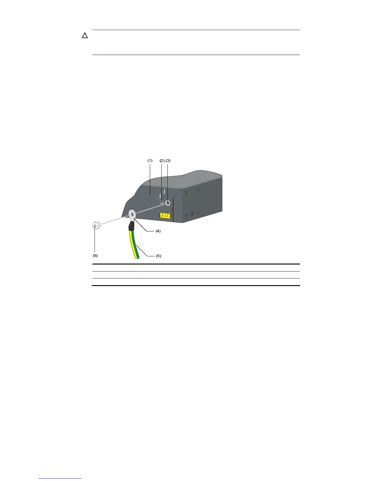
Follow these steps to connect the grounding cable:
Step1 Remove the grounding screw from the rear panel of the switch chassis.
Step2 Attach the supplied OT terminal of the grounding cable to the grounding screw.
Step3 Fasten the grounding screw, which is attached with the OT terminal of the grounding cable, into the
grounding screw hole with a screwdriver.
Figure 21 Connect the grounding cable to the grounding hole of switch
(1) Rear panel of the switch (2) Groundin
Follow these steps to attach the other end of the grounding cable to the grounding strip:
Step4 Cut the grounding cable to a proper length according to the distance between the switch and the
grounding strip.
Step5 Peel 5 mm (0.20 in) of insulation sheath by using a wire stripper, and then insert the naked metal part
through the insulation covering into the end of the OT terminal.
Step6 Secure the metal part of the cable to the OT terminal with a crimper, and then cover it with the insulation
covering. Then heat the insulation covering with a blower to make it completely cover the metal part.
Step7 Connect the OT terminal to the grounding pole of the grounding strip, and then fasten it with a hex nut.

 Loading...