EasyManuals Logo

HP V1910 Series User Manual

HP V1910 Series
44 pages
To Next Page IconTo Next Page
To Previous Page IconTo Previous Page
Page #24 background imageLoading...
Page #24 background image
17
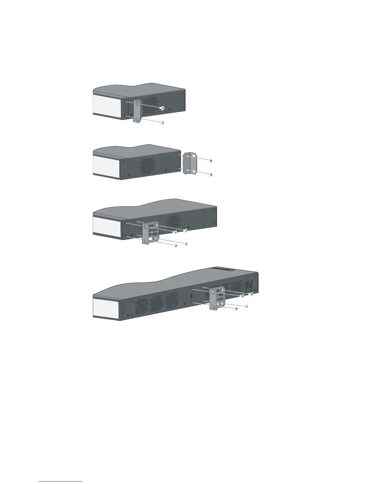
As shown in Table 14, the mounting brackets can be attached to the switch for front, center, or rear
mounting. You can choose a proper position according to the actual requirements.
Follow these steps to install a mounting bracket to the chassis:
Step1 Align the mounting holes of the bracket with the holes of the chassis, as shown in Figure 14~Figure 18.
Step2 Fasten the screws.
Figure 14 Install a mounting bracket on the chassis (A)
Figure 15 Install a mounting bracket on the chassis (B)
Figure 16 Install a mounting bracket on the chassis (C)
Figure 17 Install a mounting bracket on the chassis (D)

Table of Contents

Questions and Answers:

Question and Answer IconNeed help?

Do you have a question about the HP V1910 Series and is the answer not in the manual?

HP V1910 Series Specifications

General IconGeneral
ModelHP V1910 Series
Ports8, 24, or 48
Uplink PortsVaries by model
Switching CapacityVaries by model (Up to 104 Gbps)
Forwarding RateVaries by model (Up to 77.3 Mpps)
LayerLayer 2
ManagementWeb-managed
VLAN SupportYes
QoSYes
MAC Address Table Size8, 192 entries
Jumbo Frame SupportYes
Power SupplyInternal
Power ConsumptionVaries by model
DimensionsVaries by model
WeightVaries by model
Operating Temperature32°F to 113°F (0°C to 45°C)
Operating Humidity10% to 90% (non-condensing)

Related product manuals