Component locations
The following illustration and table identify workstation system board components.
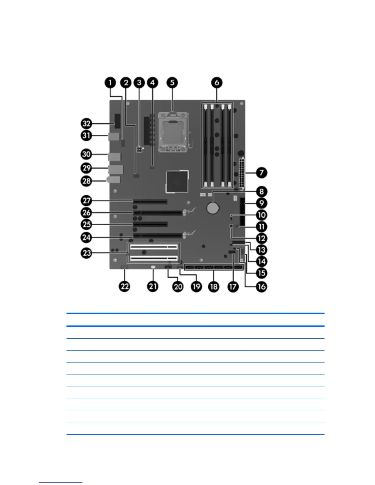
Figure 5-1 4-DIMM configuration system board components
Table 5-2 4-DIMM system board components ID
Item Component Item Component Item Component
1 CPU fan 12 Clear CMOS button 23 PCI 32/33
2 Rear chassis fan 13 Front power button/LED 24 PCIe2 x16
3 CPU power 14 Crisis recovery jumper 25 PCIe x8(4)
4 Solenoid hood lock 15 Front chassis fan 26 PCIe2 x16
5 CPU socket 16 HDD LED 27 PCIe2 x8(4)
6 Memory sockets 17 Internal USB 1/DASH 28 Audio
7 Main power 18 SATA ports 29 Network/USB
8 Battery 19 Internal USB 2 30 USB
9 Floppy disk drive 20 Front USB 31 Keyboard/mouse
ENWW
Removing and installing components
73